Advanced Sheet Metal Design Using NX Cad Challenge_7_ Metal bracket-II
METAL BRACKET
OBJECTIVE
To design a metal bracket from a 2D drawing
METHODOLOGY
DESCRIPTION
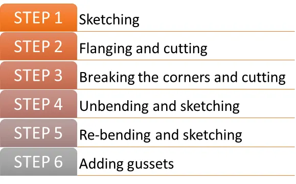
Step 1: Sketching
A sketch is drawn on the yz-plane for the front view and another on the xz plane.
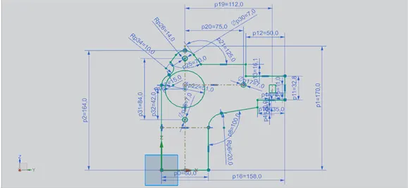
Step2: Flanging and cutting
Feature Used: Flange & Normal cut
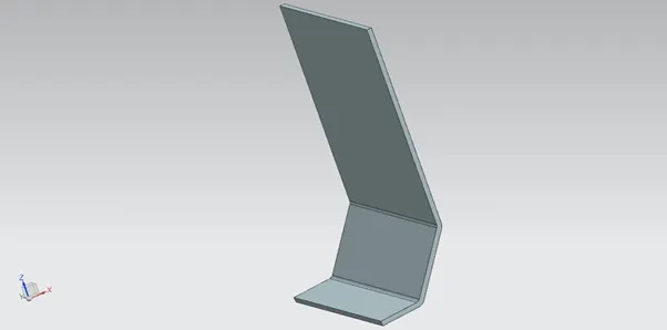
A contour flange of width of 158 mm and 3mm thickness is created from the previous sketches
The top edges are normal cut for a depth of 120 mm and 49 mm
Step 3: Breaking the corners and cutting
Feature Used: Break corner & Normal cut
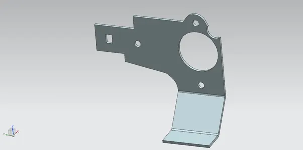
The corners are broken for 4.5 mm radius and again normal cut for 60 mm depth.
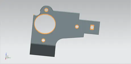
Step 4: Unbending and sketching
Feature Used: Unbend
The model is unbent to sketch the bottom hole on yz-plane and normal cut for 36 mm depth.
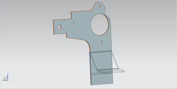
Step 5: Re-bending and sketching
Feature Used: Re-bend & break corners
The model is re-bent and the corners are bent for 10 mm, 5 mm and 12 mm. An advanced flange is added to the top for 5 mm.
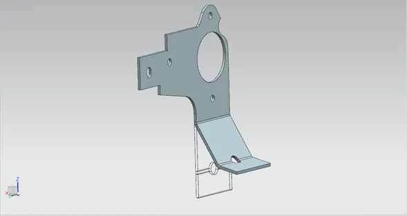

Step 6: Adding gussets
Feature Used: Holes & gusset
Two holes of 6 mm diameter are created on bottom face and two pair of gussets are created for a depth of 5 mm, die radius 2 mm, width 8 mm and side angle 45° along the bends.
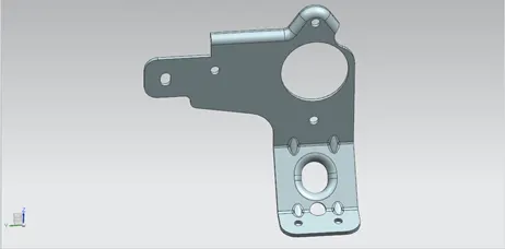
MODEL IMAGES
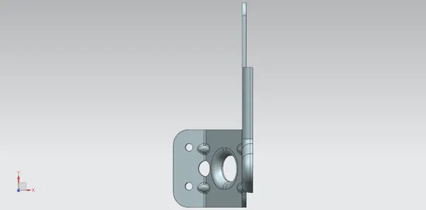
Top View
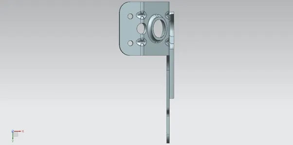
Bottom View
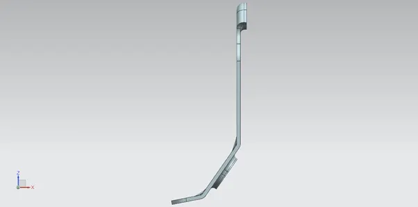
Front View
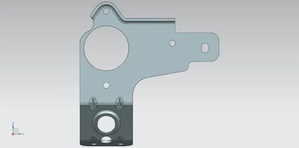
Side View
Isometric View
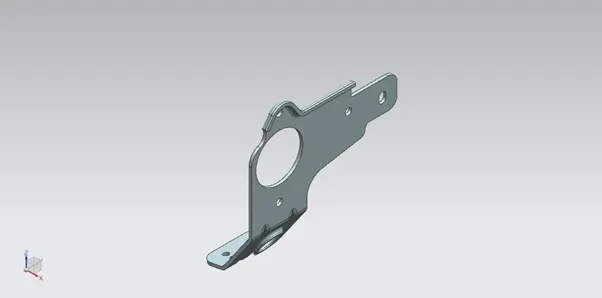
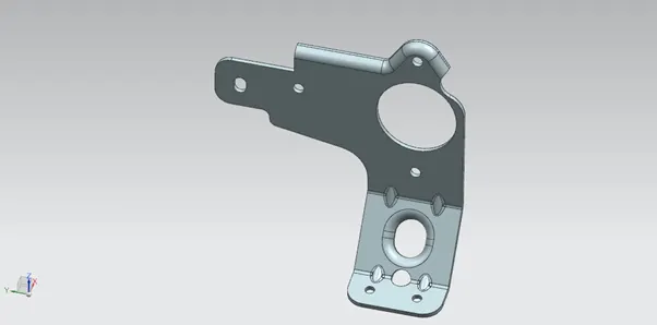
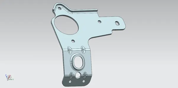
DRAFT SHEET
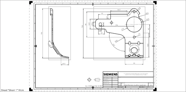
CONCLUSION
A metal bracket is designed from a 2D drawing using Siemens Nx