Advanced Sheet Metal Design Using NX Cad Challenge_7_ Metal bracket-II
Design a Metal Bracket With Different Features.
Objective: Using NX CAD to create a sheet metal bracket with numerous features and being familiar with the various sheet metal design elements needed to create sheet metal components for industrial use.
Introduction: Different engineering techniques, such as die casting, stamping, or forging, are used to make metal brackets. Sheet metal is used to shape objects from a metal sheet via punching, cutting, stamping, and bending. An accessory used to sustain loads or any attachment to a structural part is called a bracket. It is secured to the supporting component via a bolted joint or riveted junction.Sheet metal components are perfect for end-use applications due to their durability (e.g. automotive applications). The most cost-effective parts are those utilised in low volume manufacturing runs and high volume manufacturing runs due to high initial setup and material expenses. "Sheet metal" refers to any metal that may be formed into flat pieces of various thicknesses. Plates are substantial metal objects. The sheet metal industry uses a variety of metals, including cold-rolled steel, mild steel, stainless steel, tin, nickel, titanium, aluminium, brass, and copper. To design the sheet metal, we employ programmes like Creo, NX, Catia, and others of a comparable nature. The most frequent type, depending on the product and manufacturing procedure, is straight brake sheet metal forming. The NX design environment's NX Sheet Metal provides a set of tools that make creating sheet metal components quick and simple.
Design methodology:
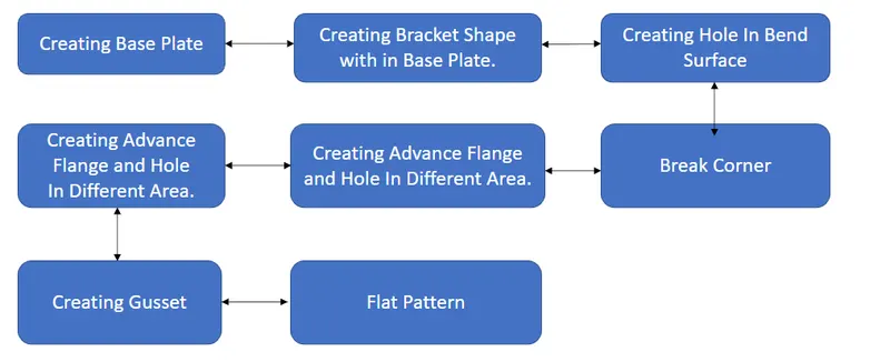
Description: Bracket Design
Step 1: Creating Base Plate
Tools Used:
Sketch: Sketch generates a 2D visual for the model when there are many sketch commands present, such as lines, rectangles, circles, etc.
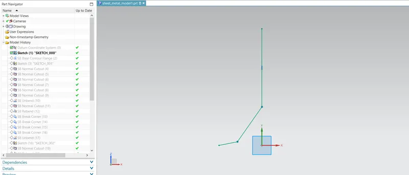
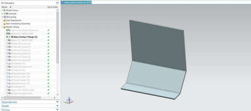
Contour Flange: extends a sketch along a vector to create a basis feature.
Step 2: Creating Bracket Shape with in Base Plate.
Tools Used:
Sketch: Sketch generates a 2D visual for the model when there are many sketch commands present, such as lines, rectangles, circles, etc.
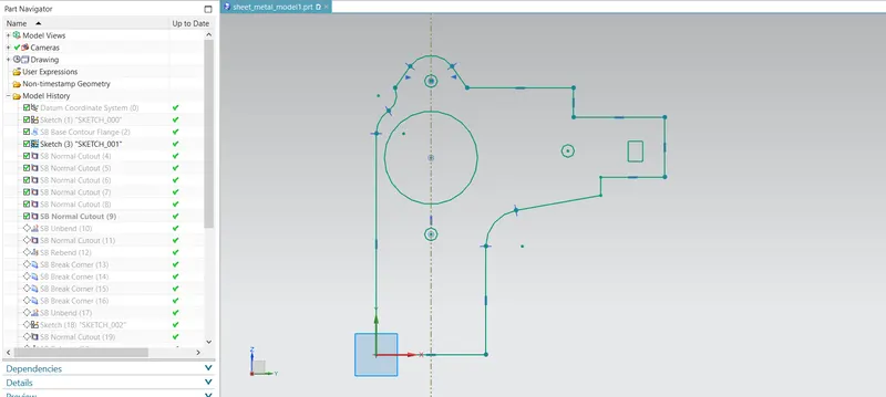
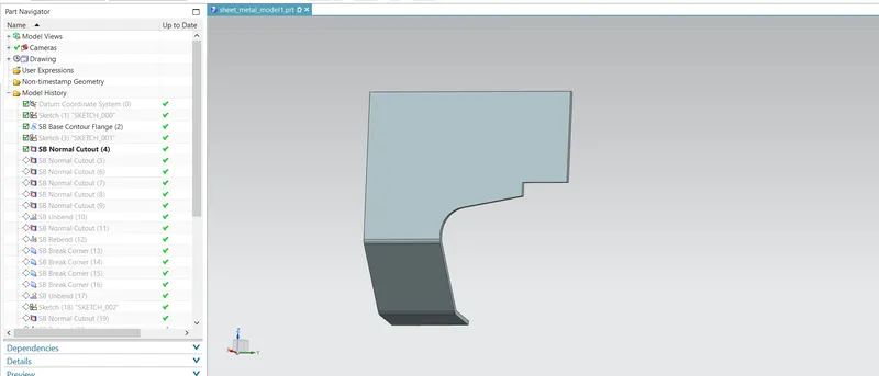
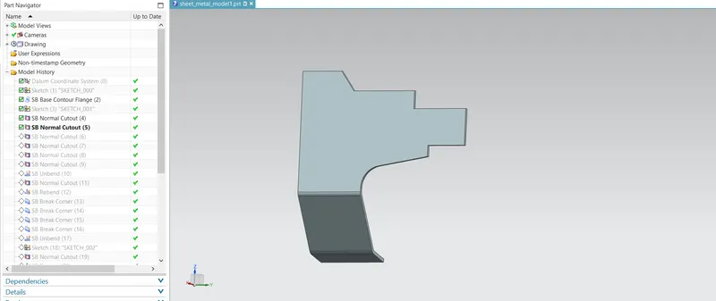
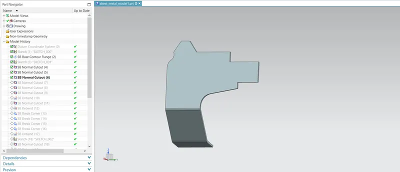
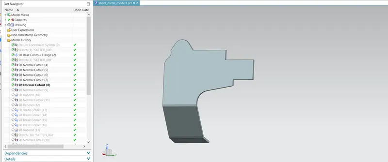
Normal Cutout: Normal Cutout commands use the principles of sheet metal manufacture to extract volumes from the sheet. Cutting faces will be parallel to the surface of the sheet metal.
NC 1:
NC 2:
NC 3:
NC 4:
NC 5:
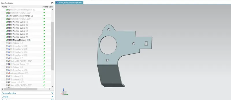
Step 3: Break Corner
Tools Used:
Brake Corner: It is the tool used to chamfer and round the Sharp edges.
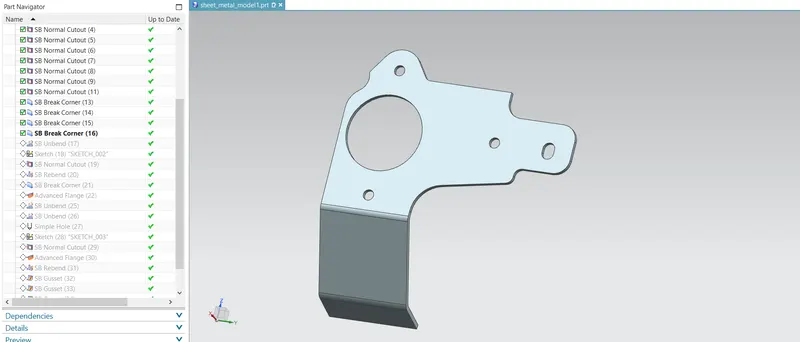
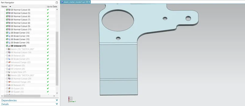
Step 4: Creating Hole In Bend Surface
Tools Used:
Unbend: Bent metal can be flattened with this feature. To add features to the bent part, we must unbend the body.
Sketch: Sketch generates a 2D visual for the model when there are many sketch commands present, such as lines, rectangles, circles, etc.
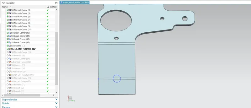
Normal Cutout: Normal Cutout commands use the principles of sheet metal manufacture to extract volumes from the sheet. Cutting faces will be parallel to the surface of the sheet metal.
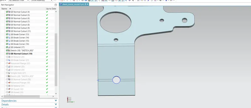
Rebend: The feature is then returned to its initially bent state after the characteristics have been added.
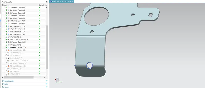
Step 5: Creating Advance Flange and Hole In Different Area.
Tools Used:
Advance Flange: A flange can be created in any non-linear surface using this commend.
Unbend: Bent metal can be flattened with this feature. To add features to the bent part, we must unbend the body.
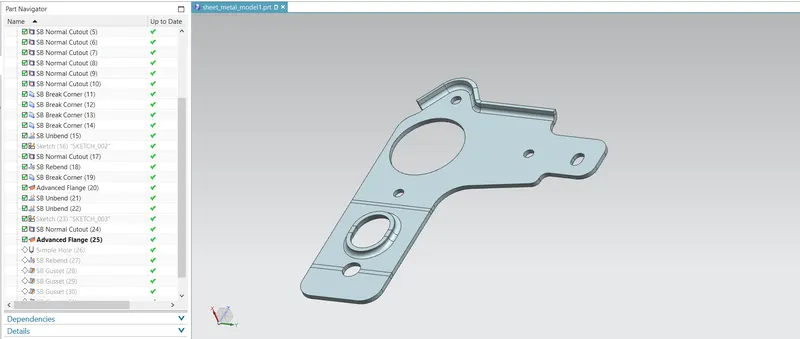
Hole: On the sheet metal model, holes of various shapes are made using hole.

Rebend: The feature is then returned to its initially bent state after the characteristics have been added.
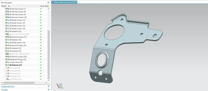
Step 6: Creating Gusset
Tools Used:
Gusset: Gusset is used to a creat a piece of fabric incorporated into a garment to strengthen or expand a particular area.
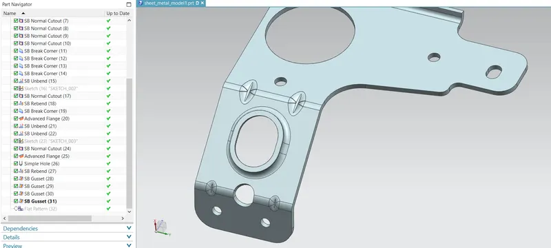
Step 6: Creating Flat Pattern
Tools Used:
Flat Pattern: A flattened pattern of the sheet metal item is made to be used in drafting.
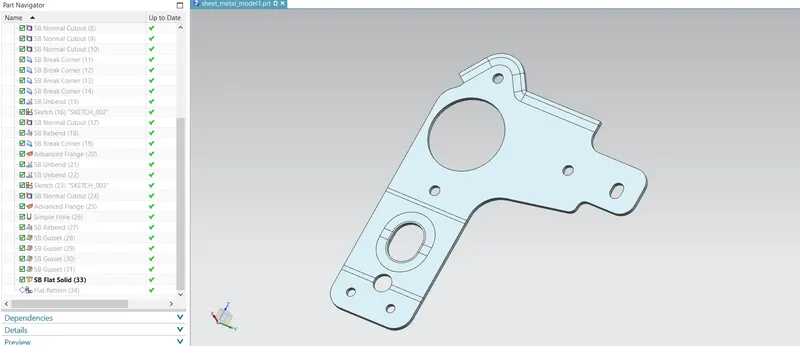
Views:
Isometric View
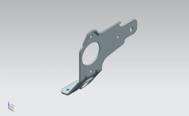
Front View
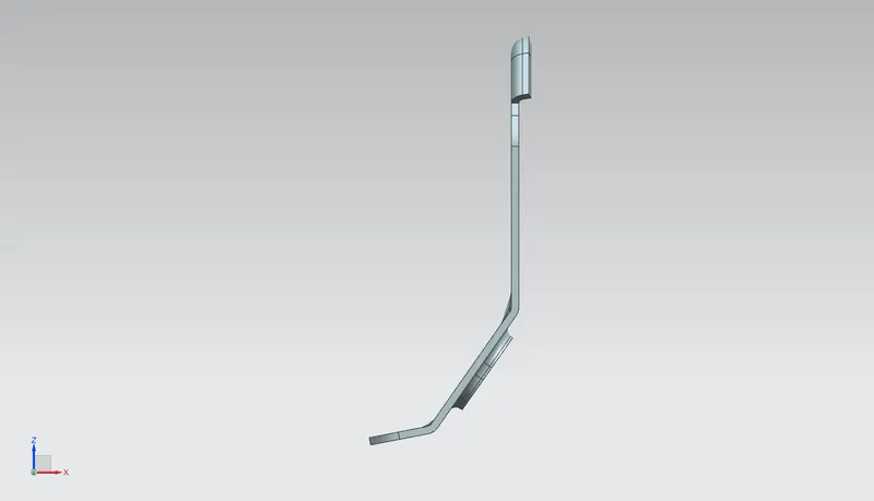
Left View
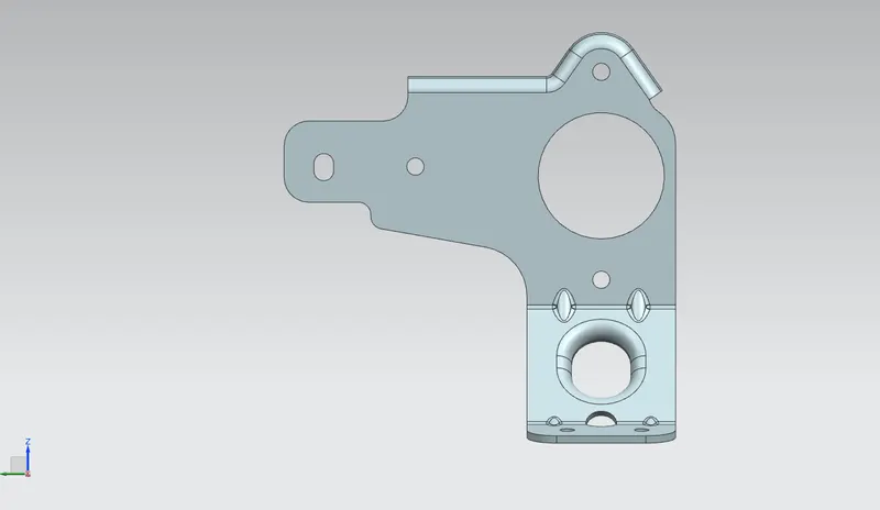
Right View
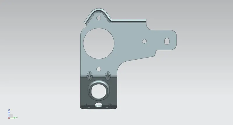
Top View
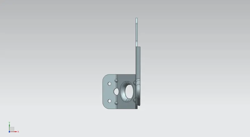
Drafting:
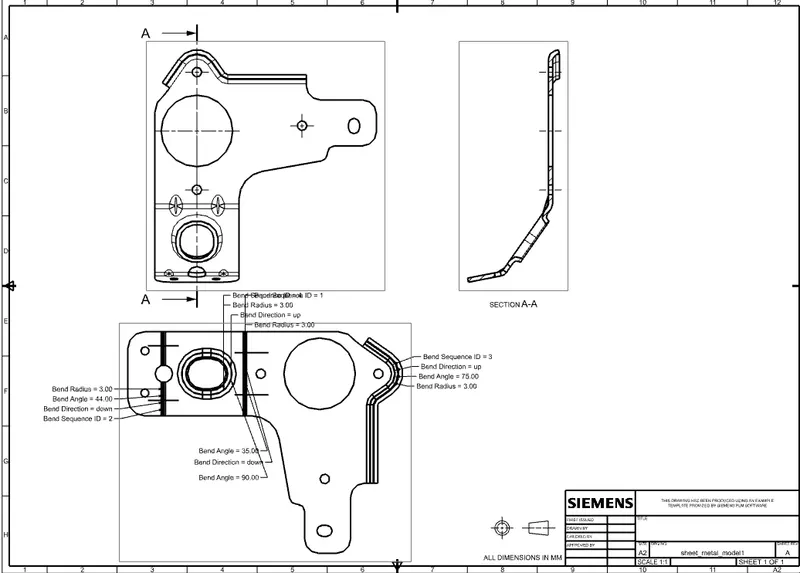
Conclusion: As a result, the braket design is produced with advance flange and gusset using NX with the required dimensions.