Advanced Sheet Metal Design Using NX Cad Challenge_7_ Metal bracket-II
Objective:-To design of sheet metal bracket-II.
Introduction:-A bracket is an architectural element. It can be made of wood, stone, plaster, metal or other media. It projects from a wall, usually to carry weight and sometimes to strengthen an angle. In mechanical engineering a bracket is any intermediate component for fixing one part to another, usually larger part. what makes a bracket a bracket is that it is intermediate between the two and fixes the one to the other. Brackets vary widely in shape but a prototypical bracket is the L-shaped metal piece that attaches a self to a wall. Its verticle arm is fixed to one element and its horizontal arn provide outwards and holds another element.
Design Methodology:-
- Create sketch
- Use Contour flange
- Normal cut out to get the required shape.
- Provide break corner at the edges to prevent sharp edges.
- Unbend the bracket and provide holes and obtony shape an the bracket.
- Now rebend the bracket and give advanced flanges.
- Finally provide gussets to increase the strength of the bracket.
Feature used :-
- Sketch
- Contour Flange
- Normal Cutout
- Corner Break
- Unbend
- Hole
- Rebend
- Advanced Flanges
- Gussets
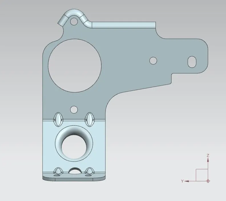
Different views of Metal Bracket-II
Isometric View
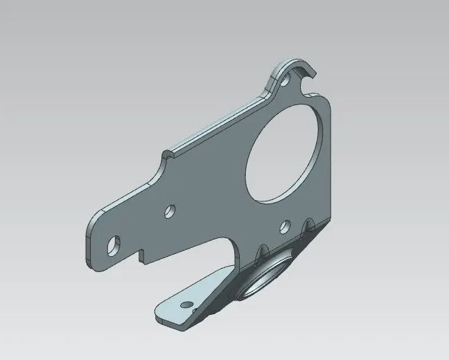
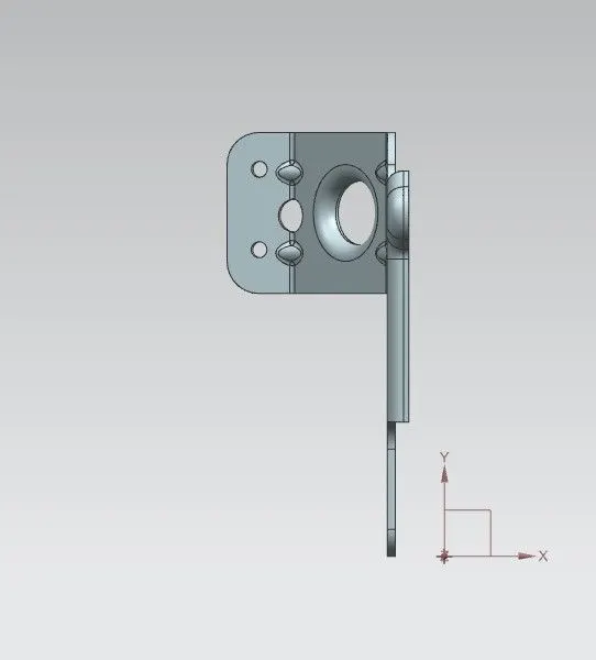
Top View
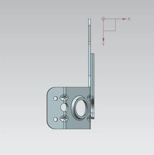
Bottom View
Front View
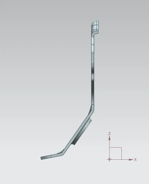
Side View
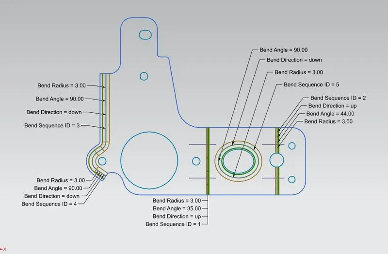
Flat Pattern
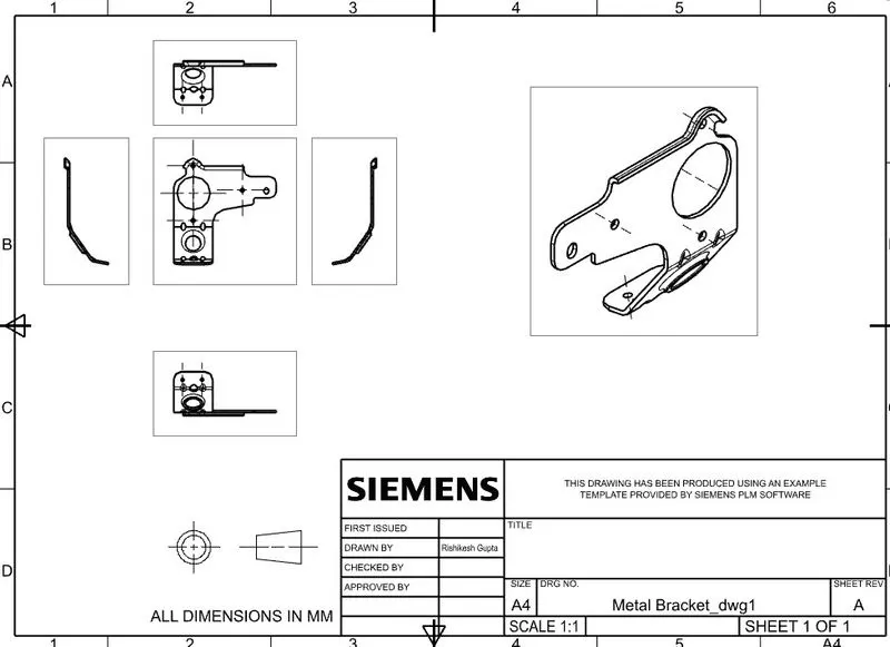
Drawing
Conclusion:- Finally, The required sheet metal bracket is modelled with the correct skill set, knowledge and the operation with Nx_Cad.