Advanced Sheet Metal Design Using NX Cad Challenge_7_ Metal bracket-II
METAL BRACKET USING NX SHEET METAL APPLICATION
OBJECTIVE:
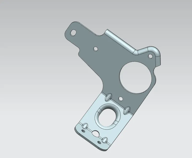
This is a project to learn the step by step procedure to create a Bracket with a gusset from the given 2D drawing.
INTRODUCTION
Sheet metal is metal formed by an industrial process into thin, flat pieces. Countless everyday objects are fabricated from sheet metal. Thicknesses can vary significantly; extremely thin sheets are considered foil or leaf, and pieces thicker than 6 mm (0.25 in) are considered plate steel or "structural steel".
We can also quickly convert solid models to sheet metal components, and create sheet metal parts that enclose other components.
NX Sheet Metal provides a set of tools within the NX design environment that allows for simple and fast design of sheet metal parts, dependent on their material and manufacturing process, the most common of which is straight brake sheet metal forming.
NX sheet metal design software incorporates material and process information in sheet metal-specific modelling features: bends, flanges, tabs, cutouts, beads, dimples, louvers, corner and edge treatments, patterns and other formable features.
NX Sheet Metal-specific features such as flanges, tabs, jogs, corner conditions, and drawn cutouts & many more along with productivity enhancements such as - automatic bend reliefs.
So, in this project I am going to design a Bracket by using sheet metal tools and commands.
DESIGN METHODOLOGY
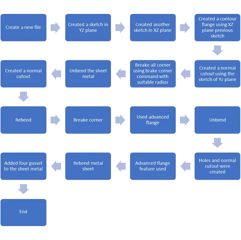
DESCRIPTION
- Sketch
Sketch creates the 2D drawing for which the model is to be designed. It consists of several sketch tools like line arc,rectangle, spline etc.
- Contour Flange-
In Siemens nx sheet metal contour flange command used to create a base feature by extruding a sketch along a vector, or adds material by sweeping a sketch along an edge or chain of edge.
- Normal Cutout-
Normal Cutout command extract volumes from sheet metal by using sheet metal production principles. Cutting faces will be perpendicular to the sheet metal surface.
- Break Corner-
This feature is used to smoothen the harmful corner of the sheet or to give an attractive look to the part.
- Unbend-
This feature is used to flatten the sheet metal part for further design operations.
- Rebend-
Rebend feature is used to get the original bend shape after performing forming operations like a dimple, bead.
- Advanced Flange-
This command is used to add a flange along an edge using a bend angle or a reference face. The edge and reference face can be curved. This command is useful when we want to create non-linear flanges, or when we work with sheet metal support structures in complex assemblies. We can use existing geometry as a reference to define the flange dimensions.
- Gusset-
Gussets are stiffening features created across a bend to reinforce the sheet metal part.
- Flatt Pattern-
This feature is used to create an instance of the flat shape and size of the sheet metal that required to create the final part.
VIEWS
Front view
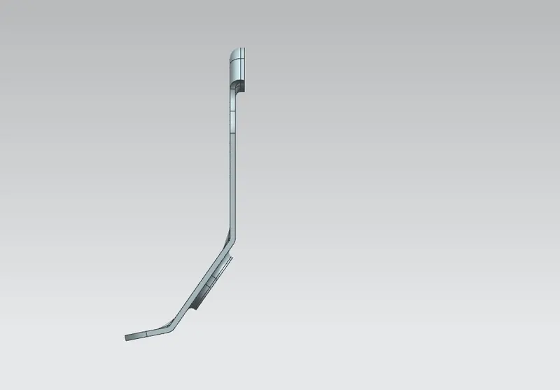
Side view
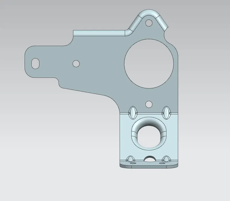
Top view
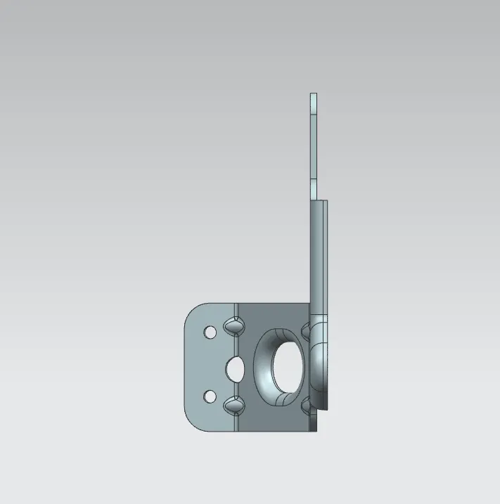
Isometric view
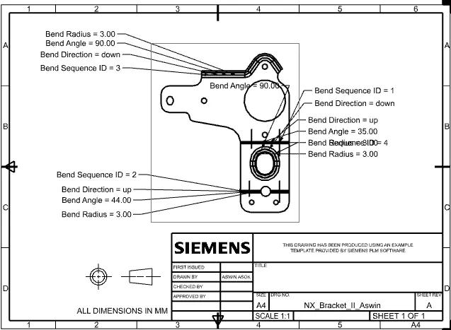
Drawing sheet
CONCLUSION
The structure of the metal bracket is obtained using basic feature of NX sheet metal application.