Advanced Sheet Metal Design Using NX Cad Challenge_7_ Metal bracket-II
OBJECTIVE:
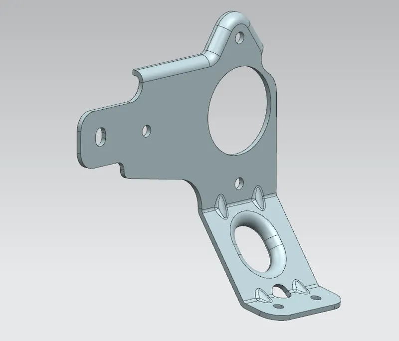
The main objective of this project is to design a sheet metal bracket in NX Cad sheet metal application workbench.
INTRODUCTION:
The sheet metal application in NX CAD provides an enviorment for the design of sheet metal parts used in machinery,Automotive and Areospace.Enclosures ,Brackets and the other parts are normally manfactured with break press.The sheet metal application widely used every industry i.e mining,construction,farming,catering,hospitality,shipping,manufacturing,aviation,medical and transport.
In sheetmetal application we can create uniform thickness parts using basic features such as flange , tabs,and jogs.the complex sheet metal part can be designed in the solid model work benchand can be converted to sheet metal part. We can also import ,clean up and covert a non cheet metal part into a sheet metal part.Flat pattern sheet metal data can be used for manfacturing process . the material parameters such as thickness bend radii and bend relief can easily set as default settings
Bracket is an intermediate component used to fix one thing (like a shelf) to another (like a wall). It may be thought of a kind of fastener, but this is somewhat misleading: actual fasteners like screws are used to connect the bracket to the other parts.
In addition to creating a connection between two parts, a bracket may provide support. Some brackets, such as gusset brackets, are designed with a diagonal section that reduces the strain on the bracket and allows it to support heavier loads.
One of the easiest and most cost-effective ways to make brackets, especially simple ones like angle brackets, is sheet metal fabrication. Brackets typically consist of two or more planes connected along one edge, and often to simplest way to fabricate this kind of object is to bend a flat object (i.e. a piece of sheet metal) in two or more places: the simplest example would be adding a 90° bend to a flat rectangle with a straight profile, turning it into a bracket with an L-shaped profile.
DESIGN METHODOLOGY
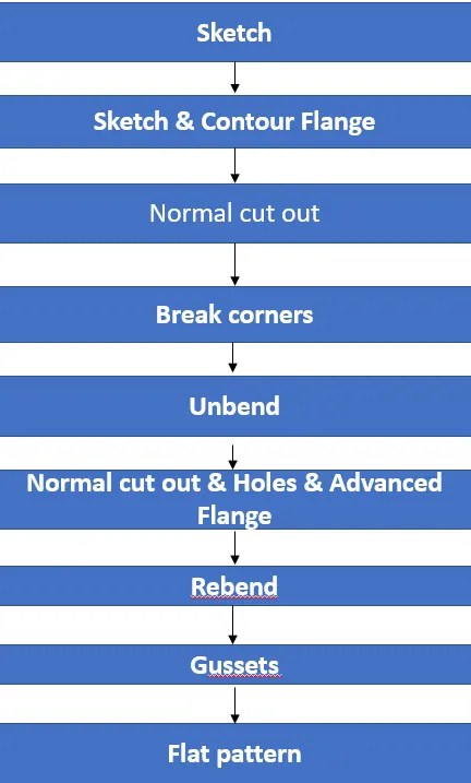
DESCRIPTION:
First sketch on YZ plane for reference of normal cutout
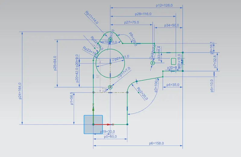
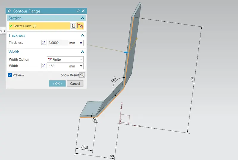
then create a required sketch/profile on XZ plane for bracket and use contour flange option as base feature.
CONTOUR FLANGE:contour flange command use to create a base feature by extruding a sketch along a vector, or adds material by sweeping a sketch along an edge or chain of edge
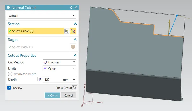
After creating base then normal cut out feature is used to cut the base sheet metal part.
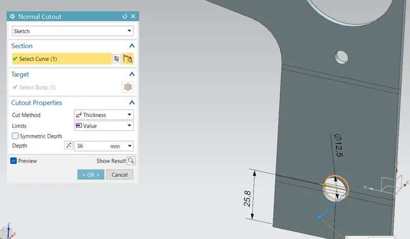
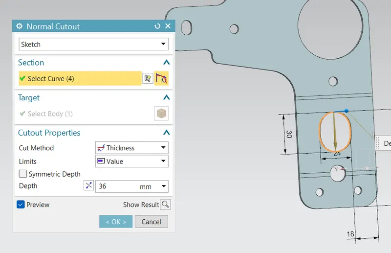
NORMAL CUTOUT: This command is used to cut material by projecting the sketch onto the model and them cutting perpendicular to faces intersected by projection.
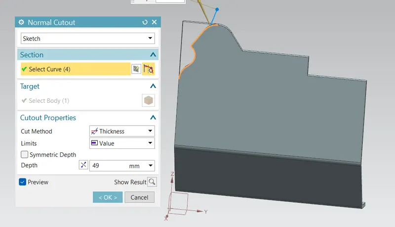
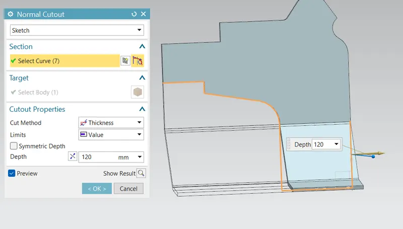
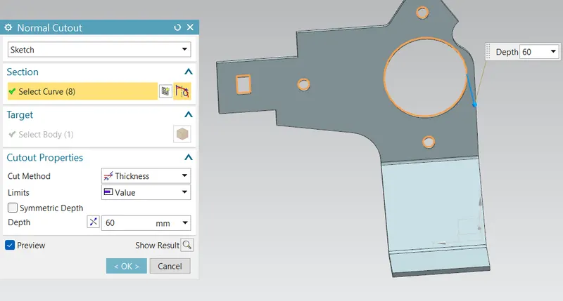
Now use break corner feature for creating smooth edges /avoid sharp edges
BREAK CORNER: This command is used to round or chamfers sharp corner of a tab or flange.
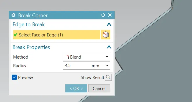
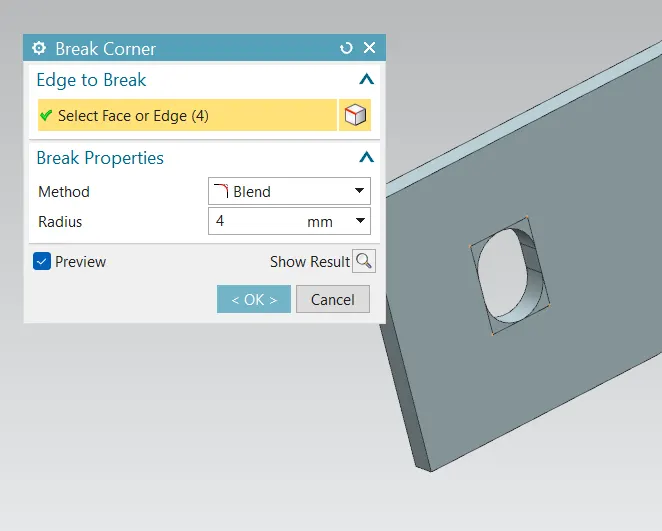
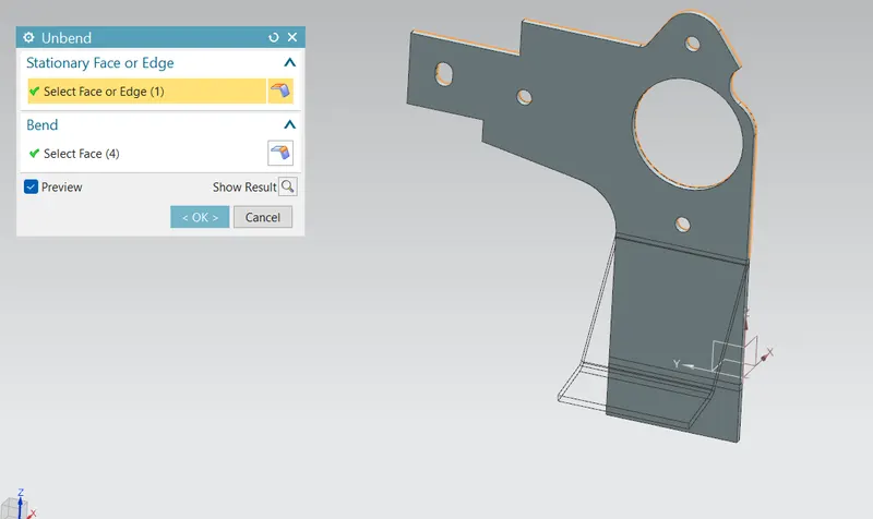
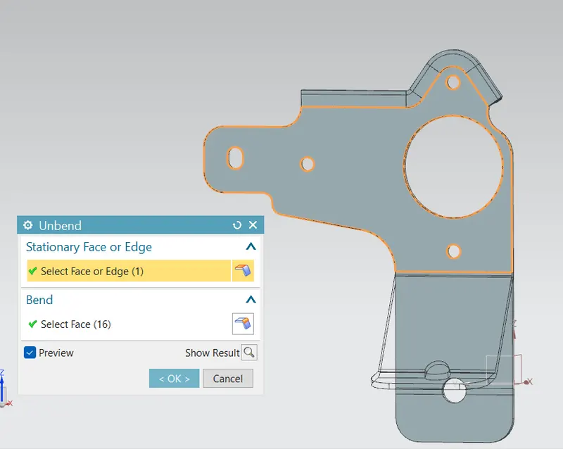
Then unbend the model for creating punch features.
UNBEND: This command is used to unbend the sheet metal. the punching operation can be performed only by unbending the sheet metal.
Here we create a sketch for normal cutout and use normal cut out option
Then use rebend option to bring midel to its orginal shape.
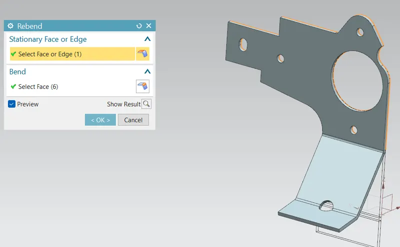
Now use break corners for the remaining sharp edges.
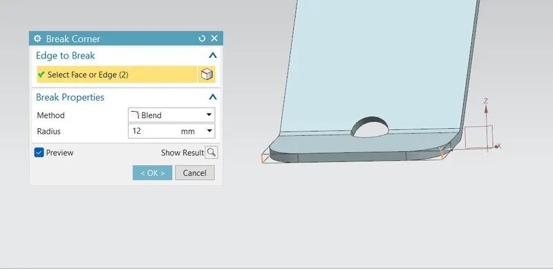
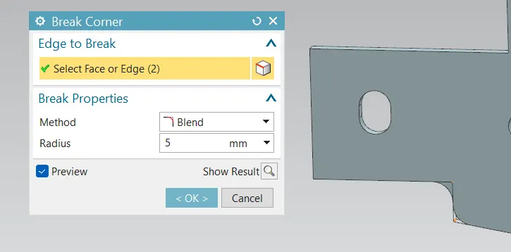
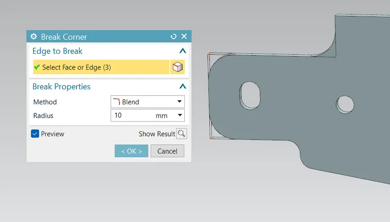
Now use advance flange option as there are curved edges.
ADVANCED FLANGE: This is similar to normal flange, difference is 1. you can specify flange end limits with plane 2. also, you can create flange with curved edges. with normal flange, you cannot create flange on curved edges.
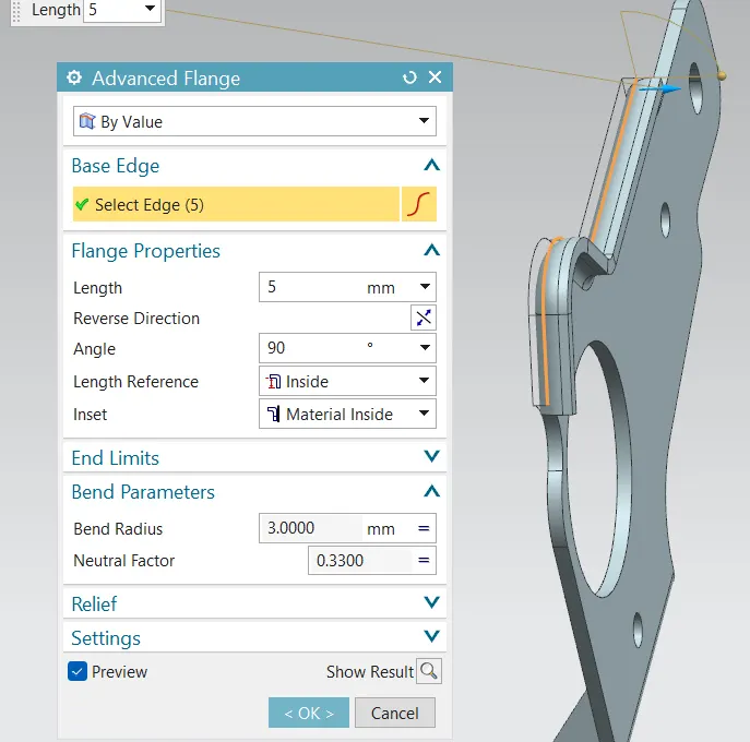
Then again umbend the part model to add some more features
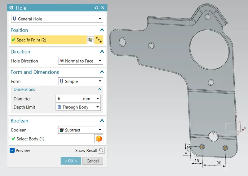
Now create a sketch to make holes.
HOLES: Adds a hole to one or more solid bodies in a part or assembly.
then create a sketch to use normal cut out feature.
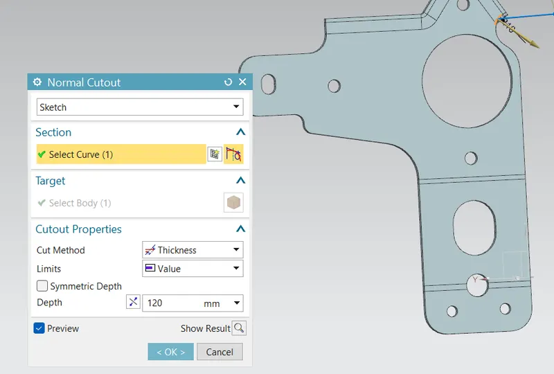
Then use Advanced flange option for curved normal cut out done previously.
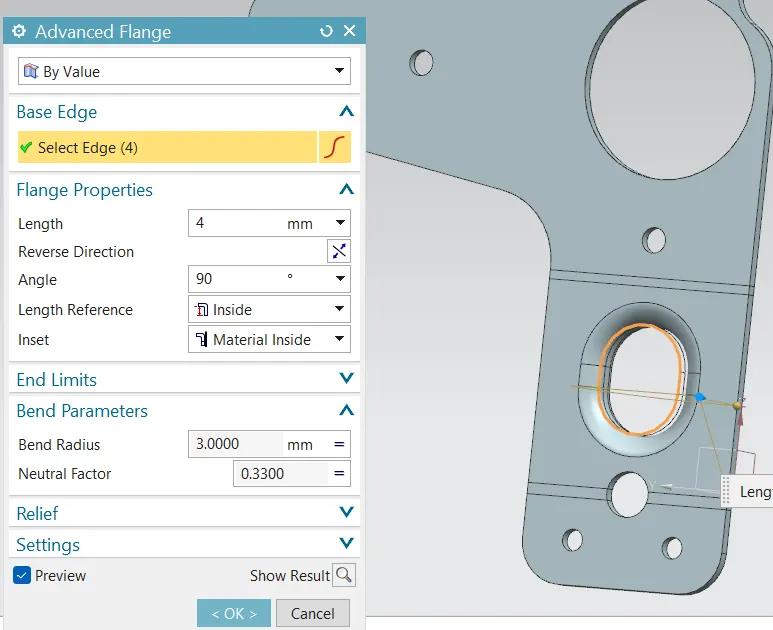
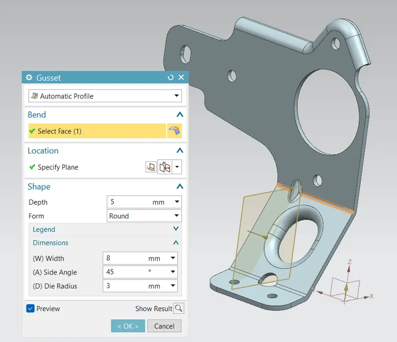
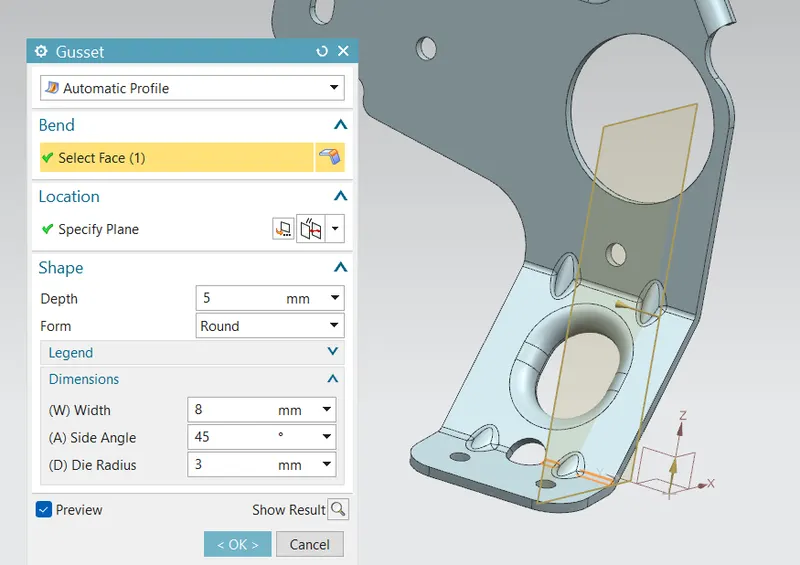
Then again rebend to bring back to orginal shape of modeland now we have use gussets option to stiffen/add strength to model
GUSSET: this feature is used tocreate a kind of embossing given to sheet metal to increase its strength
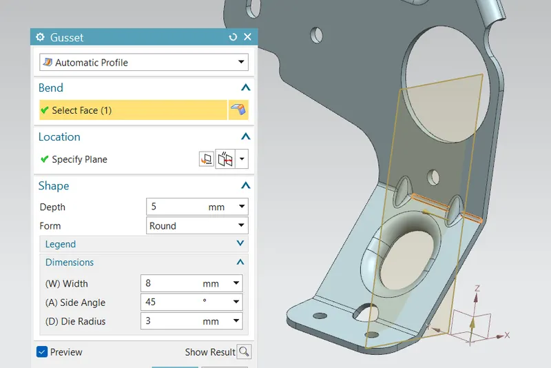
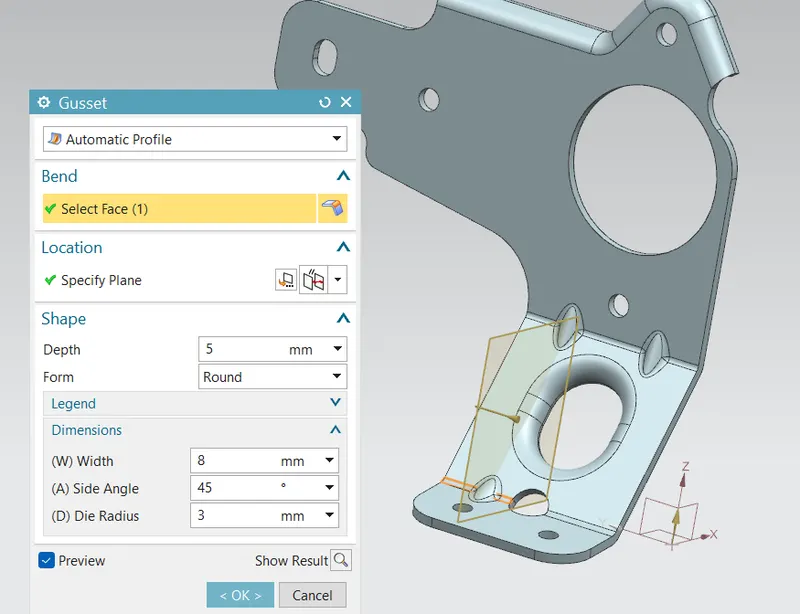
FLAT PATTERN:This is used to create a qutomatically flattened version of sheet metal parts and this is taken for drafting purpose which is used for reading model.
then go to drafting option then choose A3 sheet and oreint it to fit to sheet.
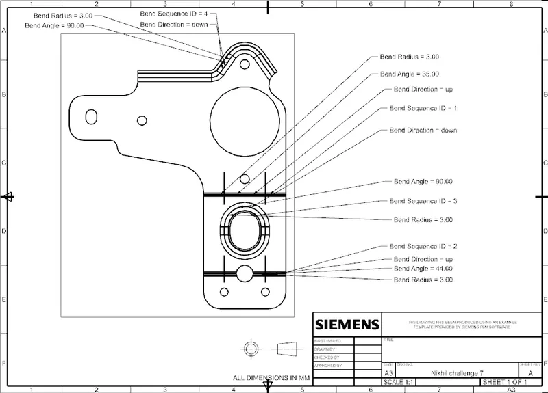
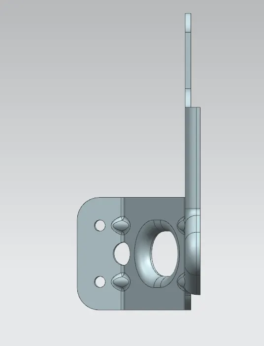
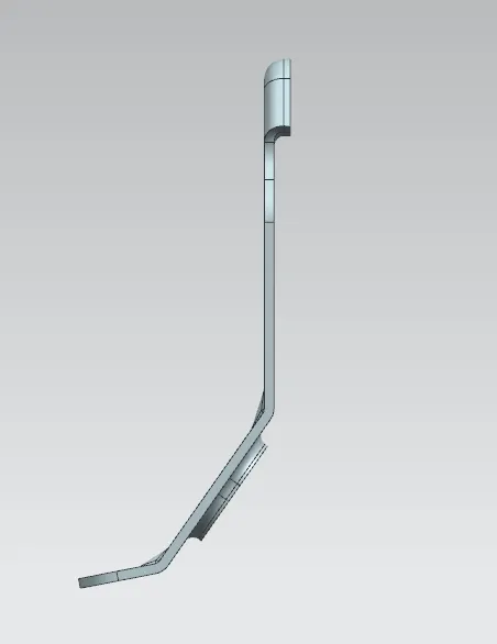
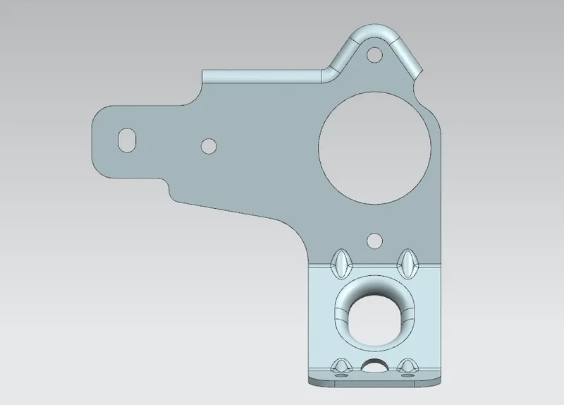
STANDARD MODEL VIEWS