Advanced Sheet Metal Design Using NX Cad Challenge_7_ Metal bracket-II
Bracket-II Report
Objective:
- To design the Bracket from the 2D sketch is used with the help of the NX Sheet metal features.
Introduction:
This design shows that the 2D Sketch to 3D Design and the add advanced feature to get strengthen the bent portions. For this design,
Design Methodology:
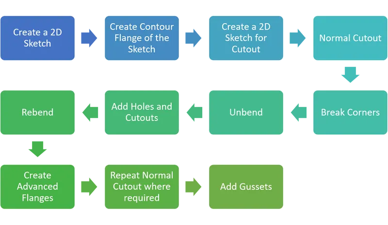
This design considers features like Sketch, Contour Flange, Normal Cutout, Break Corner, Unbend, Hole, Rebend, Advanced Flange, Gusset and Drafting. The design methodology used for this challenge can be summarized as depicted in the flowchart mentioned above image.
Features Description:
Sketch:
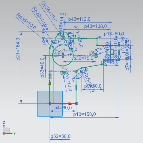
- The sketch is the basic feature and first step for creating any model. we can edit the dimensions of the sketch.
- To make the sketch we must first select the desire plane.
Contour Flange:
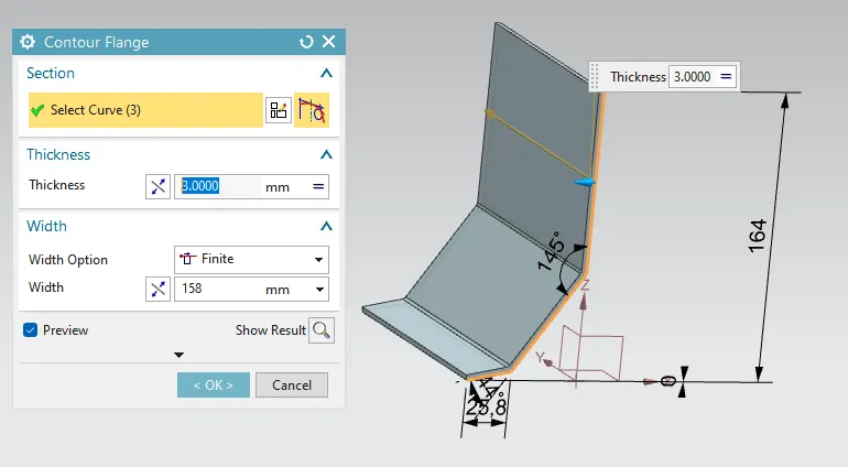
- It is used to make contour flange by using the 2d sketch.
- I created a contour flange with a length of 158 mm normal to the ZX plane.
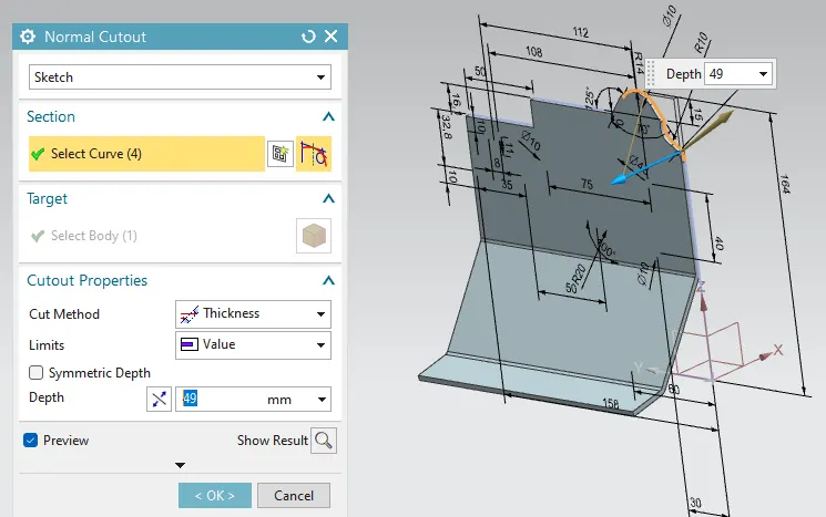
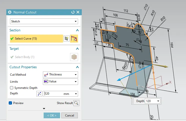
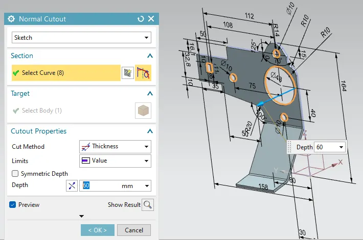
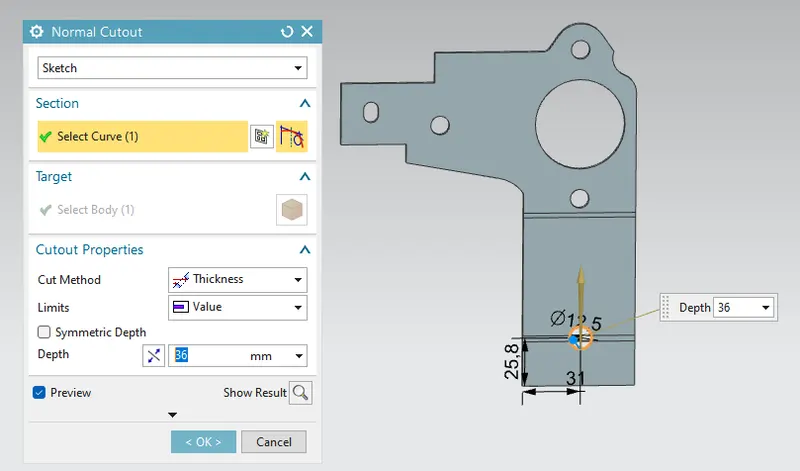
Normal Cutout:
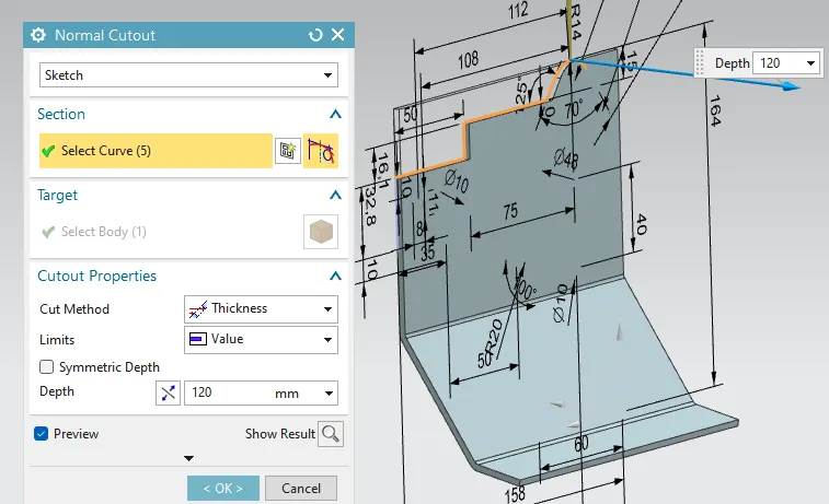
- A sketch is created on the YZ plane to cut the unnecessary portion.
- Normal Cutout is used to remove the unwanted material.
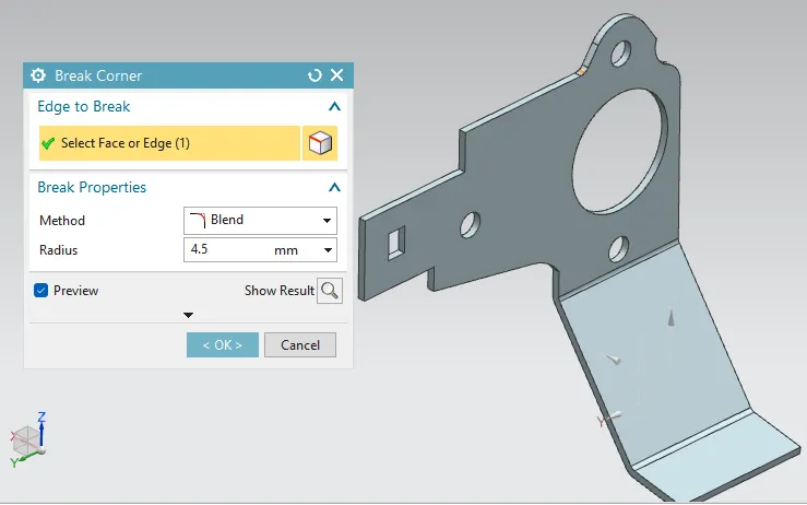
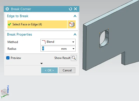
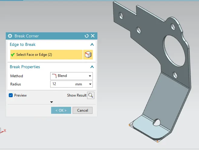
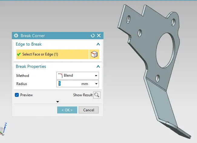
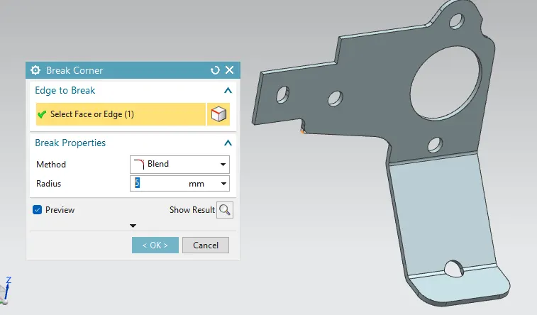
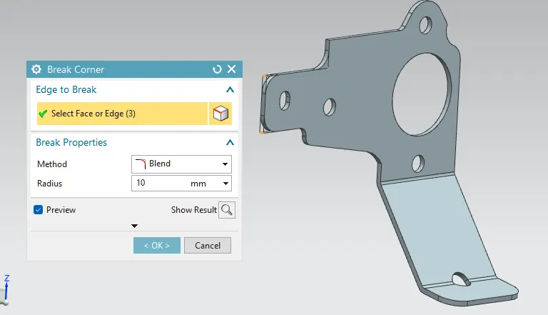
Break Corner:
- The break corner feature breaks the sharp edge in the corner and makes it round.
- Break corner helps to prevent stress relief and fracture breaking and make the smooth corner.
Unbend:
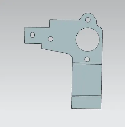
- Unbend is a very useful tool in the NX-CAD. In the Unbend dialogue box.
- select as stationary face the larger horizontal (inside the plane) face of the metal sheet.
- Select the Bend face as one of its adjacent faces.
Rebend:
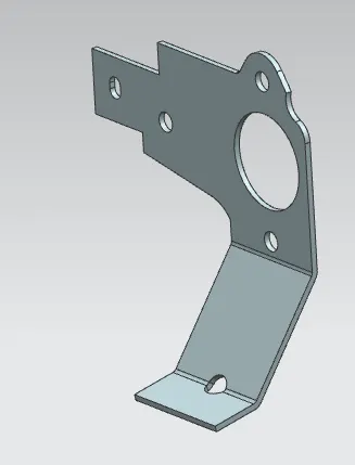
- It is used to make an original shape to a sheet metal body by using the rebend.
- Rebend is used to bend from the unbend parts.
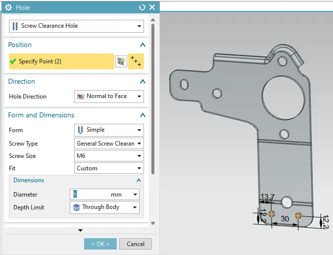
Hole:
- The hole can be created simple, with a screw clearance hole and a fit.
- set the depth limit option to through the body.
- It is used to create a hole in the sheet metal body.
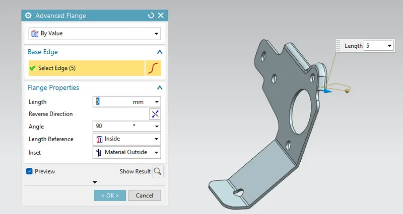
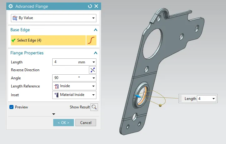
Advanced Flange:
- This feature is used to add flange along the edge by using the bend angle
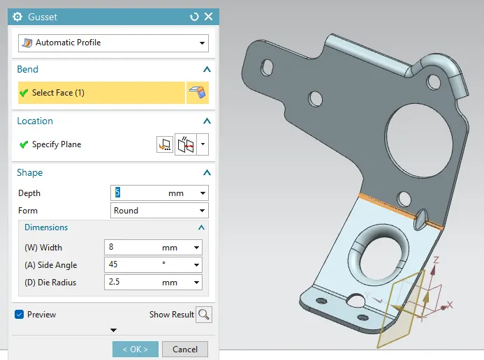
Guest:
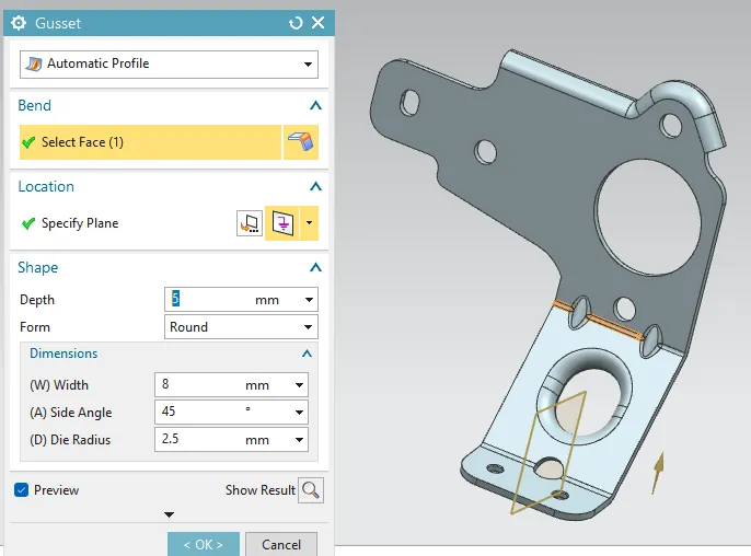
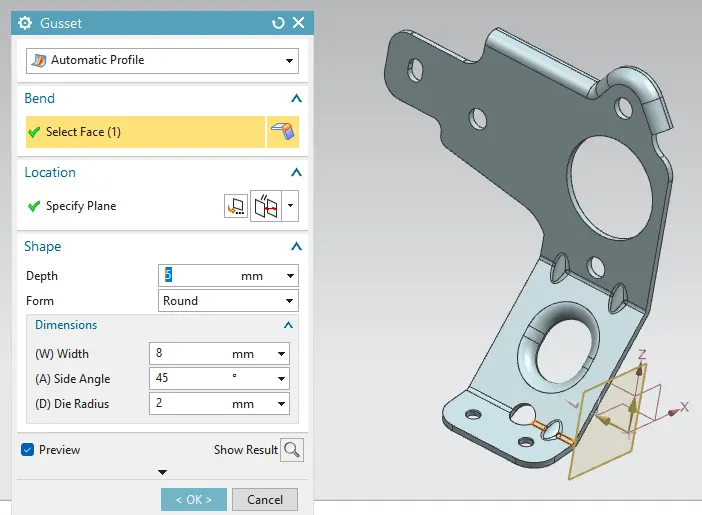
- Gussets are stiffening features across the bend to reinforce on the sheet metal part.
Drafting:
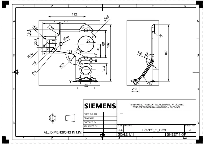
- After the modelling, the manufacturing of the component a technical 2D drawing of the component with accurate dimensions or scales is denoted.
- The draft is created with a scale of 1:1 and using A4 size. and add a new Base View.
- In the Base View dialogue box, select the option Model Views are Left View and Front View.
Final Conclusion:
- Bracket-II design has been completed by using the sheet metal application in Siemens NX CAD.
- Then the required drawing sheet was created by using the draft application in the NX-CAD.
- NX-CAD is used to maintain our desired design part and to follow the features are applied as per industry workflow.