Advanced Sheet Metal Design Using NX Cad Challenge_7_ Metal bracket-II
TITTLE: DESIGN OF SHEET METAL BRACKET -ll
OBJECTIVE -
The main objective of this project is to design the sheet metal bracket-II using the siemens NX CAD software.
INTRODUCTION -
we have created a sheet metal bracket in the previous session. here we are going to create a bit complex geometry bracket from a given 2 dimensional drawings.as we know these brackets are used so many applications like tv mount.
To increasing the strength and stiffness of the sheet metal part here we are going to use gusset and flanges. it will hekp to prevent from frature failiure.
most importantly here we are going to learn about converting 2 dimensional sketches into sheet metal part.
DESIGN METHODOLOGY
It is a single sheet metal part. we can develop a sheet metal part just correctly appling all the dimensional information in a right way.
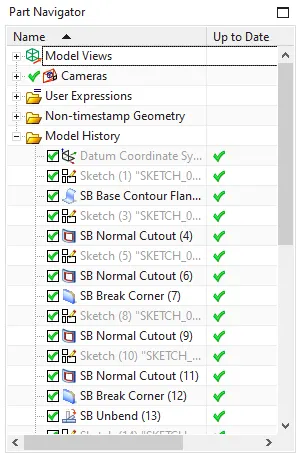
- Open the NX cad and drawn a sketch and use counter flange.
- Create normal cutout.
- Adding breakeout corner.
- Unbend.
- Create a Normal cutout.
- Rebend
- Adding breakeout corner.
- Create a Advance flnage.
- Unbend.
- Creating Holes.
- Create a Normal cutout.
- Create a Advance flnage.
- Rebend
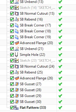
- Create a four gussets
- Create a flat pattern and change the view of flat pattern.
- Drafting.
Description:
Contour flange: This command creates a base feature by extruding a sketch along a vector.
Normal cutout: This feature cuts material by projecting a sketch onto the model and then cutting perpendicular to the faces intersected by the projection.
Breakout corner:This command creates rounds or chamfers a sharp corner of a tab or flange.
Unbend: This feature flattens the bend and a material adjacent to the bend.
Advanced flange: This feature adds a flange along an edge using a bend angle or reference face.
Hole: This feature helps to add hole in one or more solid bodies in a part or assembly with options for counterbored, countersink and threaded.
Gusset: This feature creates a stiffening gusset on a part.
Rebend: This feature restores an unbend feature to its previous bend state, along with any feature added after the unbend feature.
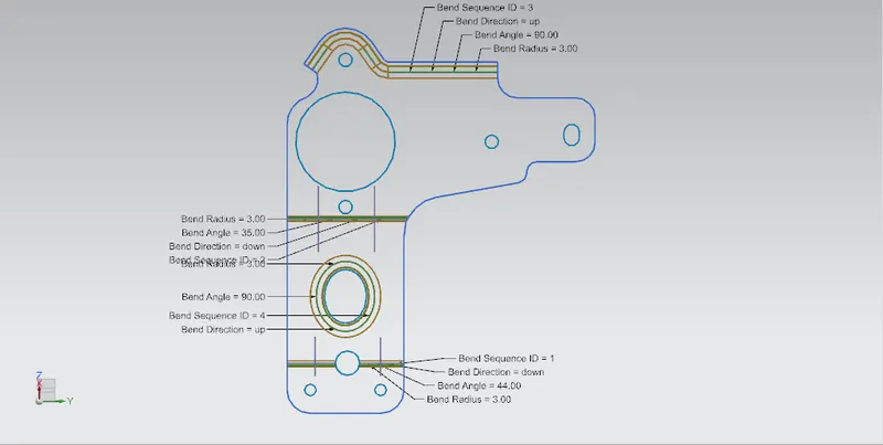
Flat pattern: This feature creates a flat pattern feature from the formed sheet metal part.
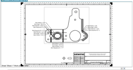
Drafting:This starts the drafting application, which provides tools to create and maintain drawings of the created model.
PROCESS STEPS -
SKETCH 1-
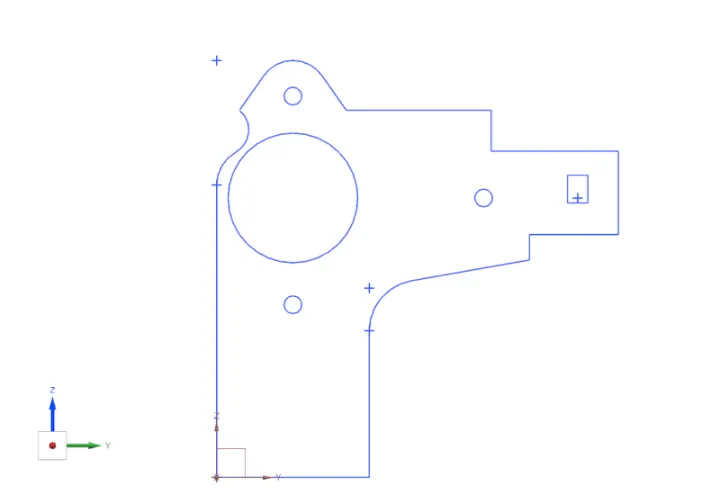
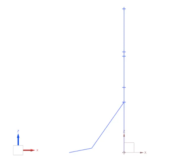
first i have created a sketch of front view on the right side plane{zy} it is up to us. i only created what i think is important. rest of the profile we can add after we bring a thickness to our sheet metal part.Then i have created a right side view sketch on the front plane where i'm going to create a contour flange.
CONTOUR FLANGE -
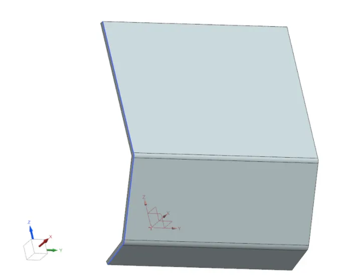
Create a contour flange by selecting a last sketch and give a uniform thickness of 3 mm.
NORMAL CUTOUT -
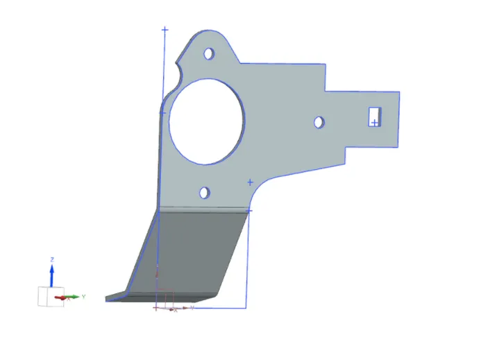
Cutout it is used to cut a bodies normal to a part plane here we are using our sketch 1 as our normal cutout profile. Final out come will look like this.
UNBEND -
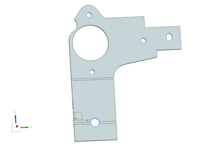
Then the next step will be un bend the sheet metal part to add some cut profile on the bend areas as shown in the figure
REBEND -
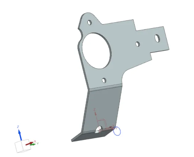
It is used to bring our part to the original position in other words to undo a unbend command.
BREAK CORNERS -
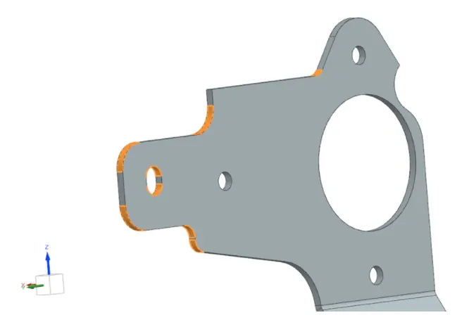
Apply break corners on the sheet metal edges to make a appropriate geometry as given the 2d diagram. It helps to provide a smooth corners instead of sharp edges.
UNBEND -
HOLE CREATION -
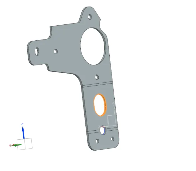
NORMAL CUTOUT -
REBEND -
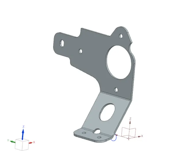
GUSSETS -
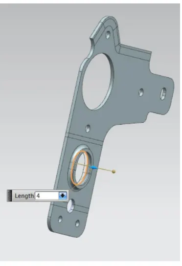
Gussets are created to improve the stiffness of the part generally gussets are created on the bend region which will connect the two faces in the specific model we are using rounded gussets pics surfaces.
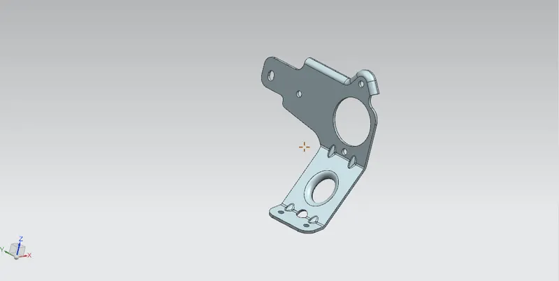
ADVANCED FLANGES -
Advanced flanges we can use this along an edge to create a flange. it is very useful where we can not create a normal flange . normal flages generally not performimg in the tangent edges. i'm not able to describe the advanced flange because i don't have a lisence to work on that.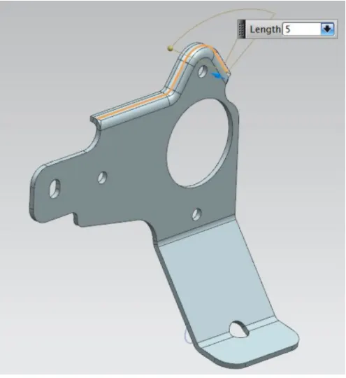
ADVANTAGES -
we can create a flange along an edge using a bend angle or reference face. the edge and the reference plane can be curved.
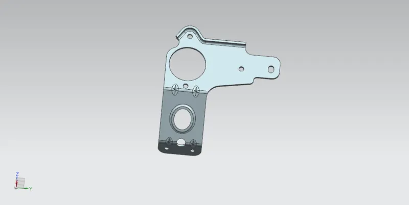
Front View -
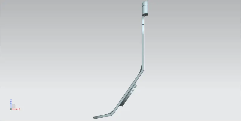
Left view -
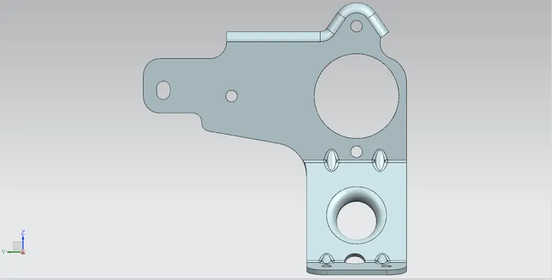
Right view -
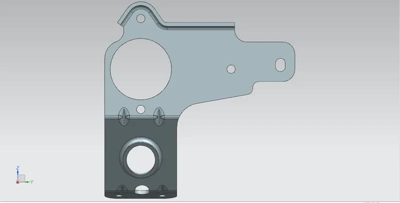
Top View-
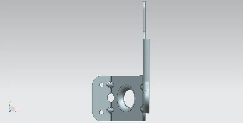
Bottom View-
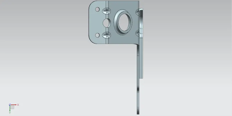
Isometric View -
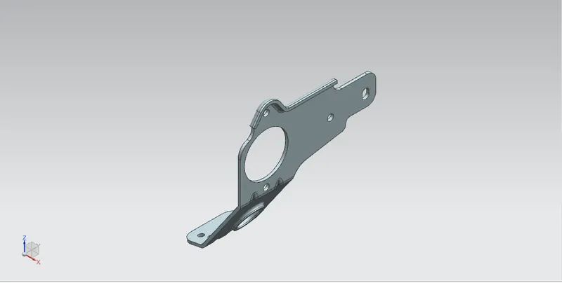
Tree Feature -
Flat Pattern -
Drawing sheet -
CONCLUSION
We hereby conclude that the sheet metal bracket-II has been designed with the mentioned parameters by using all the features in the Siemens NX sheet metal and drafting application.