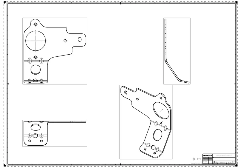
Advanced Sheet Metal Design Using NX Cad Challenge_7_ Metal bracket-II
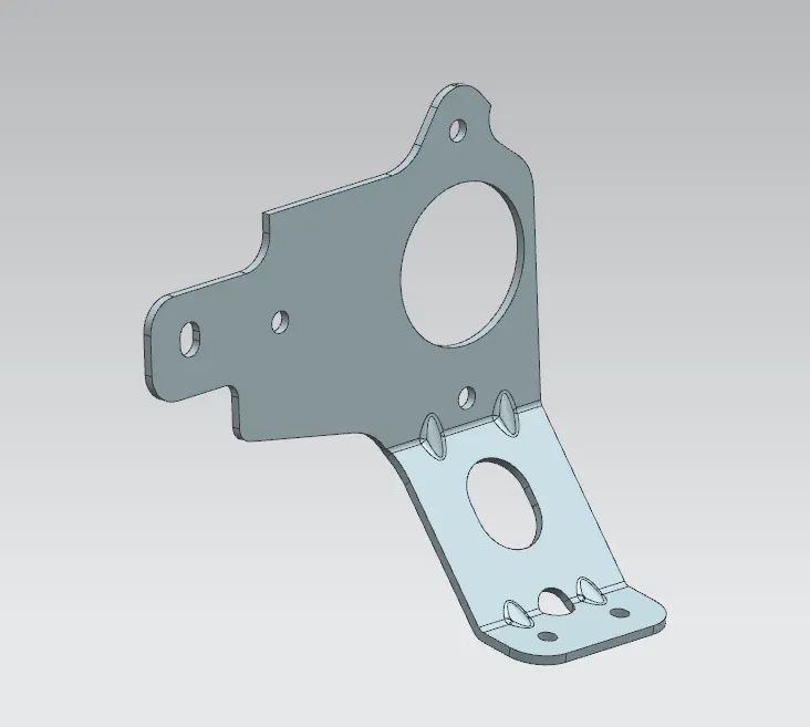
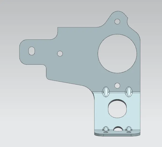
OBJECTIVE: The purpose of this project is to design the CAD model of a sheet metal BRACKET using siemens NX_CAD sheet metal workbench.
INTRODUCTION: Design of casing using sheet metal commands by adhering to standards by following the 2D Drawing. . Based on the requirements and the standards sheet metals of varying thickness are used.
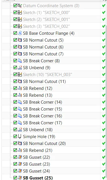
Design Tree
Commands
Tab:- This command is used to make a sheet metal base part.
Normal cutout:- This command we use to cut the sheet metal parts. Normally this command is preferred to cut the sheet metal parts.
Bending:- This command is generally used for bending the sheet metal parts.
Flange:- This command is used to create a new flange in any direction at any angle.
Break Corners:- This command is used for cutting the sharp corners or edges
Unbend:- This command is used to unfold the part.
Hole:- This command is used to make the different types of holes.
GUSSET:- Gusset It is a feature added to give stiffness to the bent sheet metal part hence increasing the strength of the part.
Bead:- This command is used to lift the material along the contour of a sketch and is similar to the simple command.
Contour Flange: The contour flange is a flange created using the open sketch created in a plane. It is different from a regular flange because it can be created in any shape and it does not require choosing the edge of any tab or existing flange.
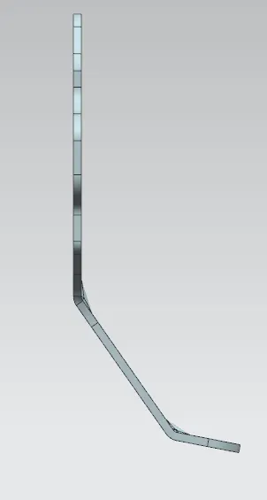
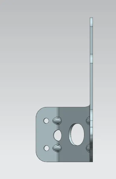
Images