Advanced Sheet Metal Design Using NX Cad Challenge_6_Bracket
OBJECTIVE:-
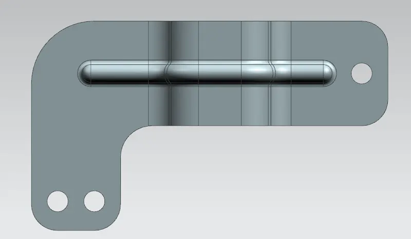
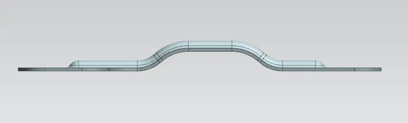
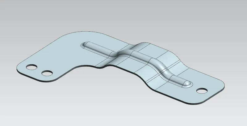
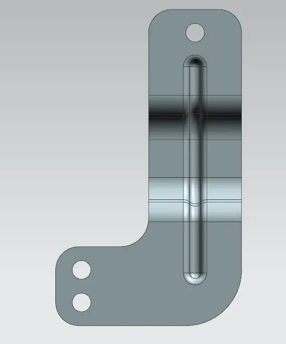
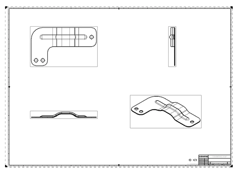
To create a bracket from the drawing using different sheet metal commands that will help to know about every single command in detail.
Introduction- Design of Bracket using sheet metal commands by adhering to standards and the 2d drawing provided
Design Tree
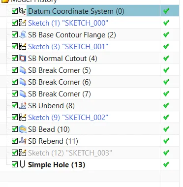
Commands
Contour Flange: The contour flange is a flange created using the open sketch created in a plane. It is different from a regular flange because it can be created in any shape and it does not require choosing the edge of any tab or existing flange. It can be at any position or at any angle. For this bracket design, a contour flange is created using the earlier sketch as the curve.
Tab:- This command is used to make a sheet metal base part.
Normal cutout:- This command we use to cut the sheet metal parts. Normally this command is preferred to cut the sheet metal parts.
Bending:- This command is generally used for bending the sheet metal parts.
Flange:- This command is used to create a new flange in any direction at any angle.
Break Corners:- This command is used for cutting the sharp corners or edges
Unbend:- This command is used to unfold the part.
Hole:- This command is used to make the different types of holes.
Dimple:- This command is used to lift the area of a model inside using a sketch.
Bead:- This command is used to lift the material along the contour of a sketch and is similar to the simple command.
Rebend:- This is used to unfold part.
Flat Pattern:- This is the final process to get the Flat pattern of the sheet metal part.
Images