Advanced Sheet Metal Design Using NX Cad Challenge_7_ Metal bracket-II
Title Of the Project:
Advanced sheet metal using NX CAD for making a metal bracket.
Objective of the project:
The main objective of this project is that to design a metal bracket of sheet metal component with the help NX CAD software with Advanced sheet metal Features.
Introduction:
NX sheet metak application provides a fast and accurate sheet metal modeling through a set of tools dependin on their strength and accuracy of the component in the manufacturing process.
The 3D software model of the sheet metal work is then used to ‘unfold’ the parts into developed, flat, bracket blanks. This process takes care of any sheet metal gauge bend allowances that will have to be applied to the specific part thickness and material type.
If done correctly this will enable the CNC bent bracket to fold back up to the correct sizes to match the original 3D sheet metal model.
This also has the advantage of removing the need to try out sample bracket parts first for simple sheet metal work as the trial work can be carried out within the software.
The next stage is to clean up any corner notches that will not suit the standard CNC tooling, ensure all the details on each face of the bracket are correct to the 3D sheet metal model and add any inspection information that might be important to the manufacturing processes for the sheet metal work.
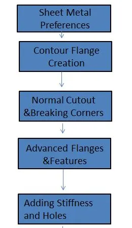
Design Methodology of Metal Bracket:
Description of the Metal Bracket:
The Sheet Metal Bracket is created is as follows.
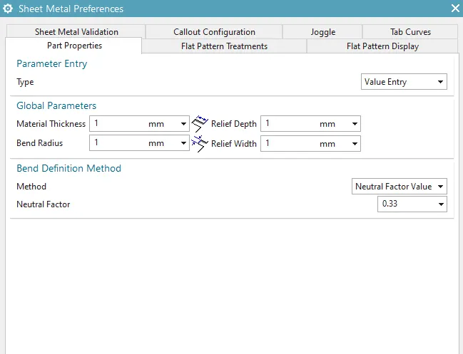
1)Sheet metal Preferences.
The primary step in creating a sheet metal bracket model is to validate the sheet metal preferences and modify the global parameters into the requirements.
The next step is to create the 2D sketch in the YZ plane that is used for defining the sheet metal features.
Normal Cutout is a command to cut the material by projecting a sketch on to the modela nd cutting perpendicular the surfaces intersected by the projections.
Break corner is a command to round or chamfer sharp corner of a tab or a flanges.
Unbend is a command used to flattened the sheet metal part wirth respect to one of its flat sheet.
Rebund is a command is used to get the back the original sheet metal part of the sheet due to unbend feature of its original shape.
Hole is a command is used to create a hole a features component.
Tab is a command used to create a base feature by extruding the sketch along the vector by adding the material to its existing face of the component with a thickness consideration.
Flange is a command is used to create a flat flanges on a tab component with respect to the specific angle and bend can be made with a edges of the component.
Bend is a command is used to bend the tab or a flange of the created part along the sketch or surfaces of the component.
Gusset is a command is be created in between the two metal sheets so yo provide a stiffness to the component and it also provides a rigidity to the sheet metal application component.
Advanced flange is a command is used to create a flange over a curved surfaces or edges of the component.
Views of the Metal Bracket as shown in the below figures:
1) Left view.
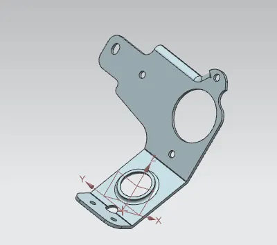
2) Trimetric view.
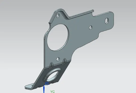
3) Top view.
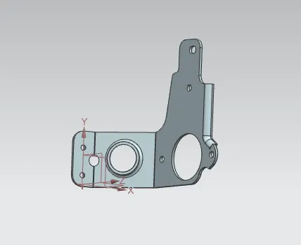
4) Bottom view.
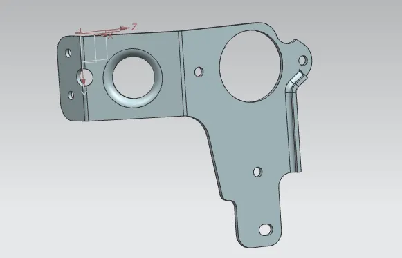
Conclusion:
The Metal bracket component is made with the proper dimensions given in the sketching elements and due to the stiffning it is provided with the gusset and for smoot finishing it is made with proper method.