Advanced Sheet Metal Design Using NX Cad Challenge_7_ Metal bracket-II
BRACKET DESIGN IN NX CAD USING SHEET METAL APPLICATION
OBJECTIVE
To create a bracket from a 2d drawing using NX CAD sheet metal application.
INTRODUCTION
A bracket is designed from given 2d drawing using basic commands in NX CAD sheet metal workbench .
DESIGN METHODOLOGY
DESCRIPTION
- Sketch - It is a 2d drawing drawn in YZ Plane
- Sketch – Another sketch is drawn in XZ plane
- Contour Flange – It helps create a Flange by extruding a sketch .
- Normal Cutout – It cuts a sketch onto a sheet body .
- Normal Cutout – It is used to cut the profiles .
- Break Corner – It is used round the sharp edges –
- Unbend – It is used to bend the figure to create additional holes .
Normal Cutout – It is used to a sketch
- Advanced Flange – It adds a flange along the edge .
- Normal Cutout – Additional features like a square were cut .
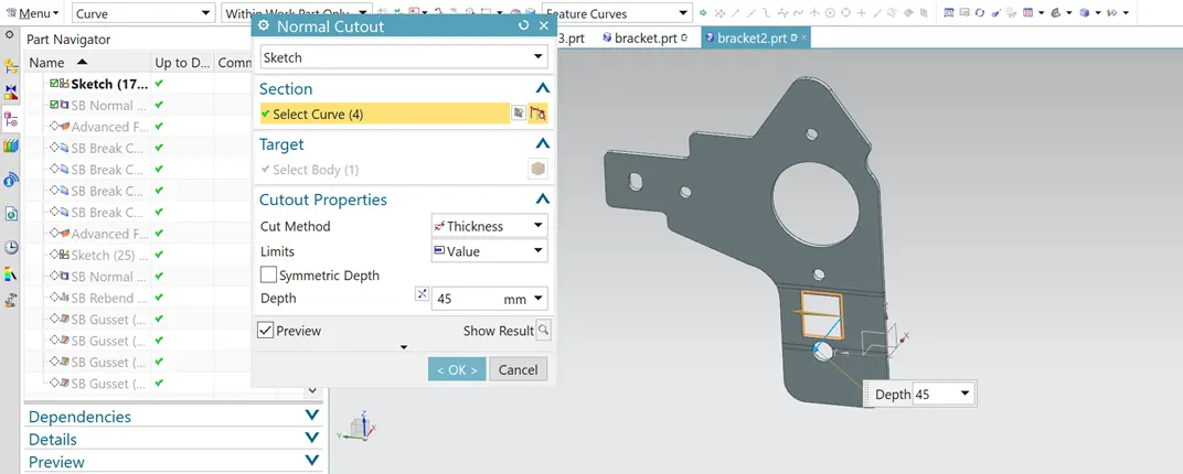
- Advance Flange – It is added to the square edges .
- Normal Cutout – Two more holes were cut .
- Rebend – After adding all features the model was rebent .
- Gusset -It is a stiffening feature added .
FRONT VIEW
TOP VIEW
SIDE VIEW
ISOMETRIC VIEW
CONCLUSION
A bracket has been created from the given 2d figure using NX CAD sheet metal application .