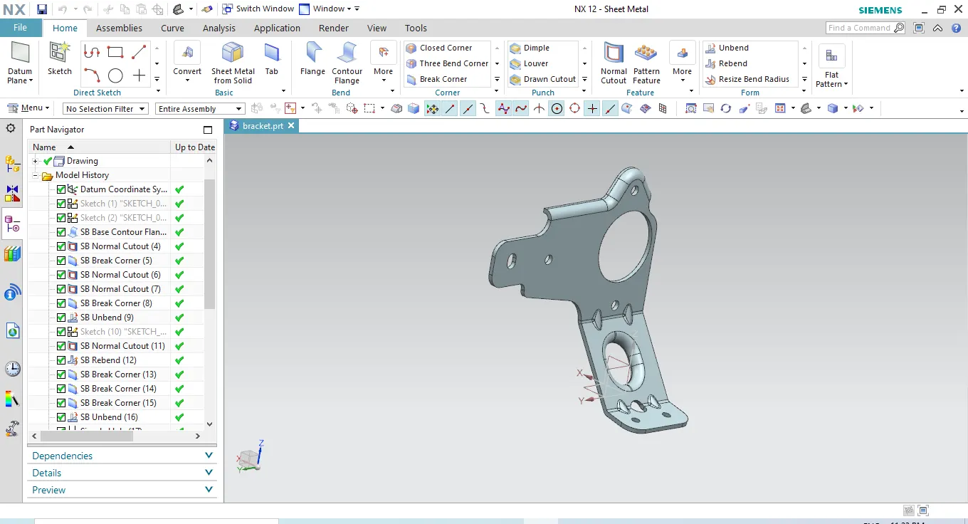
Advanced Sheet Metal Design Using NX Cad Challenge_7_ Metal bracket-II
OBJECTIVE:
To understand the step by step procedure to design the metal bracket using NX CAD
INTRODUCTION:
Sheet metal parts are known for their durability, which makes them great for end use applications. Parts used for low volume prototypes, and high volume production runs are most cost-effective due to large initial setup and material costs. Sheetmetal Brackets are manufactured by conducting stamping or die casting operation. These can be used for many application for mounting of any products like antennas to TV, projectors or street lights, etc.
DESIGN METHODOLOGY:
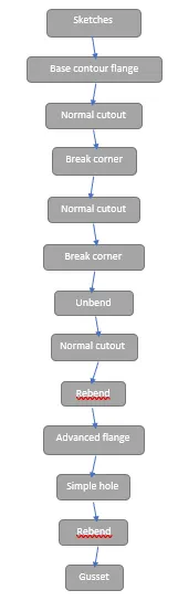
DESCRIPTION:
SKETCH - It is a basic of any design.
TAB - it is used to create base feature of a sheet metal.
Flange - it is used to create a extended part of a sheet metal.
UNBEND - This feature is used to unbend the sheet metal taking any one face as a stationary face.
REBEND - used to rebend the sheet metal.
- Advanced flanges can be made on the edges and reference faces by adding flange along an edge using a bend angle or a referecne face which can be straight or curved.
BREAK CORNER - This feature is used to provide to convert the sharp edge into rounded edges.
NORMAL CUTOUT- This feature is used to remove the material from the sheetmetal material. A profile is first drawn using the sketch feature and the material will be removed inside the sketched profile.
GUSSETS are placed on the bending areas to give strength to the metal bracket.
IMAGES: