Radar Mast & Final Assembly of Yacht
RADAR MAST
---------------------------------------------------------------------------------------------------------------------------------
ASSEMBLY OF YATCH
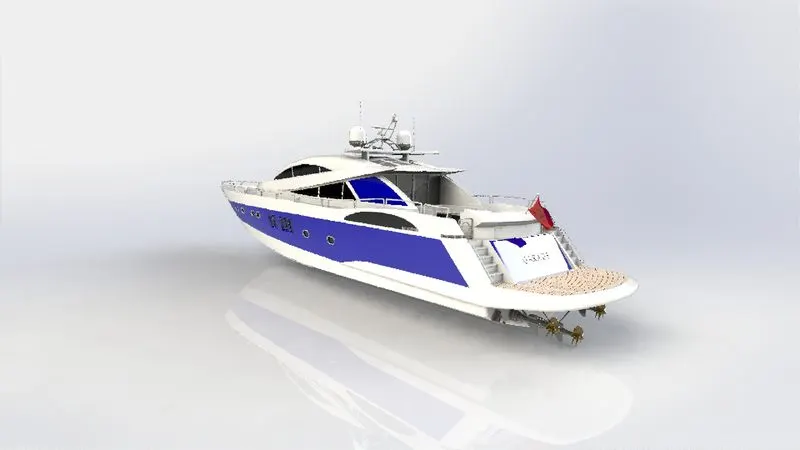
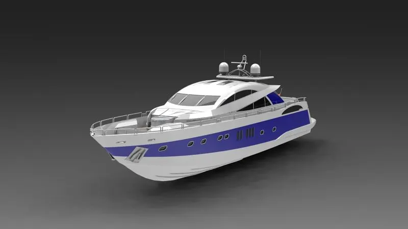
OBJECTIVE:- To design and draft the individual parts of the yatch and assemble it and render it with photoview 360.
INTRODUCTION:- A yacht is a craft used for pleasure and sport. The name comes from the Dutch word jaght, which translates as ‘hunter’, a fast, light sailing vessel used in the past by the nation’s navy to chase pirates and other ne’er do wells. When the English King Charles the Second was carried by ‘jacht’ from the Netherlands back home, in 1660, the word soon came to mean a vessel in which important people were carried, not just any old boat.
The yatch mainly consists of the following parts.
1. Propellers
2. Radar
3. Hull
4. Super structure
5. Garage door
6. Radar mast
7. Front seat
8. Middle seat
9. Rear seat
Propeller: -
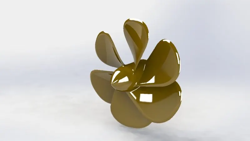
A propeller is a device with a rotating hub and radiating blades that are set at a pitch to form a helical spiral, that, when rotated, performs an action which is similar to Archimedes' screw. It transforms rotational power into linear thrust by acting upon a working fluid, such as water or air.
- For designing the propeller the main hub is created by simple sketch line and spline drawn on the front plane and extruded using the revolve option around the centre line.
- The wings are twisted parts created by sketching the two different rectangles on two different surfaces and formed into solid using loft option.
- The shape of the wings are obtained fillet applied at the two edges on top side.
- For inserting the shaft the hole is created by sketching the circle on the hub back end and material is removed using extrude cut option. Color is applied to the propeller for appearance as shown in the figure.
Radar and Radar mast-
Marine radars are X band or S band radars on ships, used to detect other ships and land obstacles, to provide bearing and distance for collision avoidance and navigation at sea. They are electronic navigation instruments that use a rotating antenna to sweep a narrow beam of microwaves around the water surface surrounding the ship to the horizon, detecting targets by microwaves reflected from them, generating a picture of the ship's surroundings on a display screen.
Radar is a vital navigation component for safety at sea and near the shore. Captains need to be able to maneuver their ships within feet in the worst of conditions and to be able to navigate "blind", when there is no visibility at night or due to bad weather. In addition to vessel-based marine radars, in port or in harbor, shore-based vessel traffic service radar systems are used by harbormasters and coast guard to monitor and regulate ship movements in busy waters.
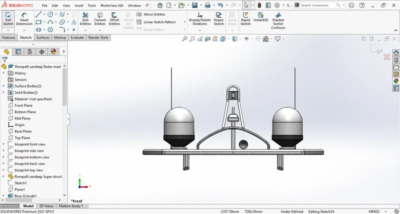
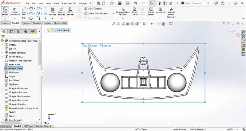
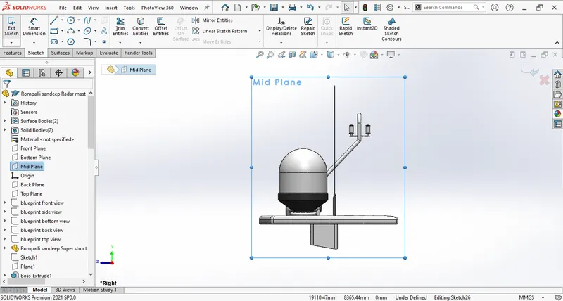
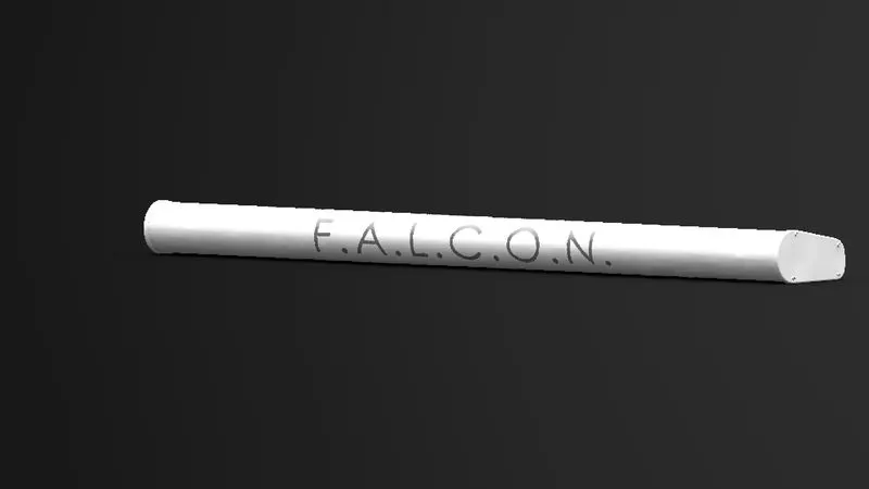
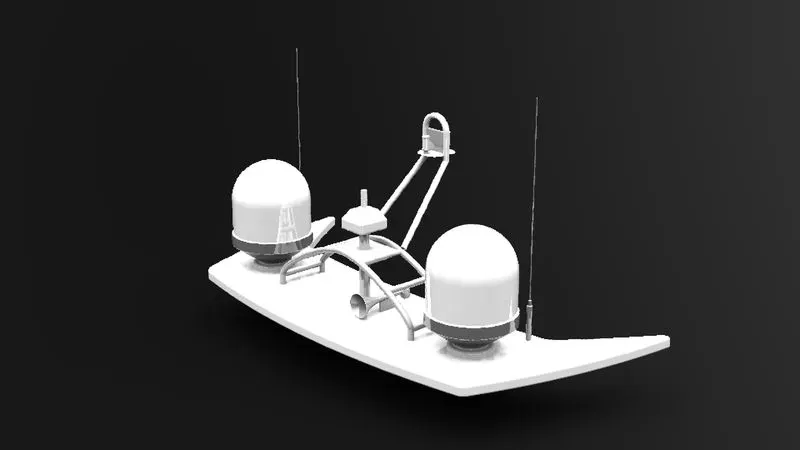
Here Radar is rotating stick which sweeps the incoming microwave signals and radar mast contains the system to produce the outgoing signals using the antenna.
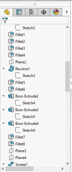
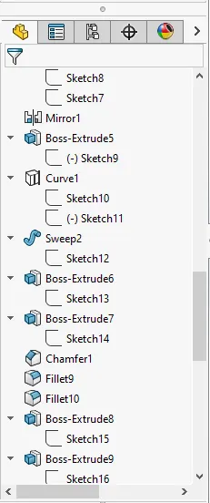
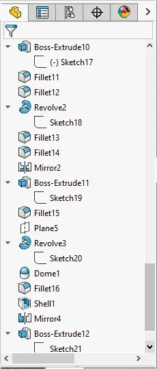
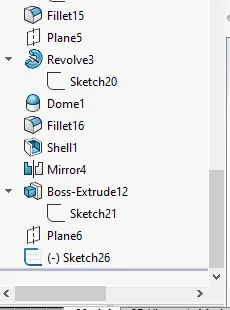
Design of this component involves base creations initially in 2D sketcher and that is being extruded in the features tab.
The lobes on two sides as shown in the picture is drawn on a plane which is created with reference to mid plane offset at a required distance and using revolve tool solid cylindrical object is formed on the base.
- Revolve: - This tool requires a closed sketch with the central axis which helps to form the cylindrical object with reference to central axis.
The antennas are the circular structures where the circle is being sketched or drafted on the base surface initially and extruded in features tab.
Horns are created on a newly created reference geometrical plane and using revolve tool circular horn is formed and the front hollow shape is been developed using shell option.
- Shell: - This tool helps to crate the shell to the solid body which prompts to enter the thickness and reform the solid object into shell type object with the wall thickness as provided.
Hull:-
A hull is the watertight body of a ship or boat. The hull may open at the top and it may be fully or partially covered with a deck. Atop the deck may be a deckhouse and other superstructures, such as a funnel, derrick, or mast. The line where the hull meets the water surface is called the waterline.
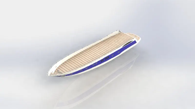
The Design of Hull involves preparation of outer shell surface and the deck surface. The outer shell is drafted with the required curves initially and are extruded and lofted, to obtain the required surface the cures are drawn on different planes and they are projected so that the required curvature is obtained in between the planes
- Curve Projection:- It is one of the option in Solid works tool which gives us the output cure for the two curves/lines drawn on different planes, this is the intersection path where the two extruded surfaces meet.
- 3D Sketch: - very handy tool to draw any line or curve in space as it is confined to the axis helps to join the projected curves and work on different axis to create geometrical planes.
- Surface Extrude:- It is used to form the surface bodies where the thickness is line thick.
- Surface Loft:- Loft is the option used to prepare very difficult surfaces formed with the help of 4 different curves drawn on different planes. It involves two profile curves and one or more guide curves.
These lofted or extruded surfaces which are in intersection are combined together with the help of Surface Knit
- Surface Knit:- It helps to eliminate the minor gaps exist between the two surfaces and join them together as like a single surface. This option works only for surfaces not for solid bodies.
The hand rail present all over the Hull top is first drafted on different planes using the convert Entities option and is designed as shown in the picture and is projected on to the surface of the Hull. These lines are converted in to tubes with the help of sweep option which requires a circle at any one of the curves/line.
- Convert Entities: - it is available in 2D sketching tab which convert the edges of the 3D object to the line projected on to the surface.
- Sweep: - It helps to produce solid tube along the guided curve/line path.
The rope for the anchors is prepared using the option helix/spiral.
- Helix/spiral:- it is used to create any springs it screw treads as this option contains pitch or height and revolutions which describes how many rings with gap between them.
Thus the half part of the Hull structure is designed and mirrored along the middle plane to form the complete closed structure. Fillets and chamfers are used to smooth the sharp edges.
Super Structure: -
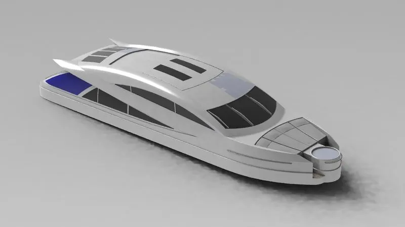
The most complicated part of the whole yacht design is its superstructure which sits on top of the deck surface.
This super structure also designed with the help of the imported blue print top, front and side views as shown in the below picture.
Initially the wall of the super structure is created by drawing a line on the bottom plane along with the curvature using the spline option and making it constrained using proper dimensions and being surface extruded in the feature manager tab.
The base wall is trimmed according the estimated design and another surface is extruded with reference to the base wall edge using ruled surface
- Ruled Surface: - It is used to obtain the extrude surface perpendicular do the plane of reference and the added advantage of Ruled surface is that the surface can tilted with and angle as prompted in the tool along with the length.
For obtaining the curves at various positions project curve option is used and they lofted together to form the required surface.
During the surface extrusion process unwanted surface are being produced which are trimmed using the Trim tool.
- Surface Trim:- This prompts to select the reference surface and next surface to be trimmed and it also options to keep the surface or remove the surface that was selected to trim.
After creating all the necessary surfaces from all the sides the surface are being knit using surface knit option to form a single body and converted in to a solid body.
The conversion of solid body only happens when there is no gaps found between the surfaces that are being extruded and trimmed.
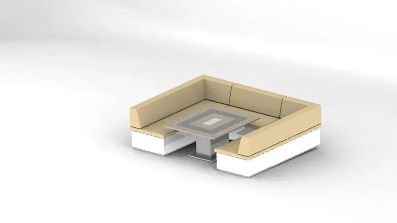
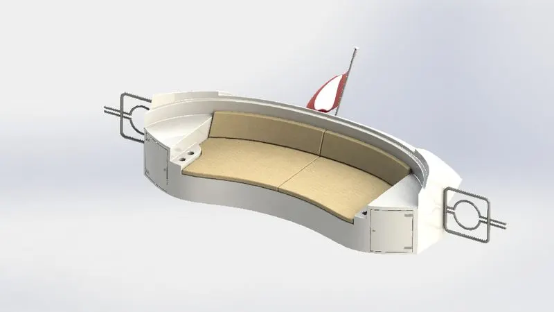
The seats attached to the super structure are extruded out from the line drawn on the mid plane and extruded up to the surface and the appearance created with the help of dome tool as shown below.
Extra appearance is obtained on top and rear side of the super structure is obtained using extrude cut option. For this the required shapes are drawn on the required plane and is cut using the offset from surface option present in the selection tool bar present in the extrude option by providing the depth of cut.
Front table created in attachment with the seats using the revolve option and appearance is given by selecting the color.
Garage Door: -
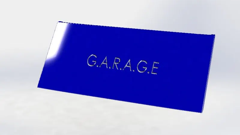
Garage is the part that is extracted from the hull structure rear part using split entities option and is been saved using different file name and it is edited to fit in the hull a cover or door to the garage space created for storing or equipments or vehicles.
Front, Middle and Rear Seats: -
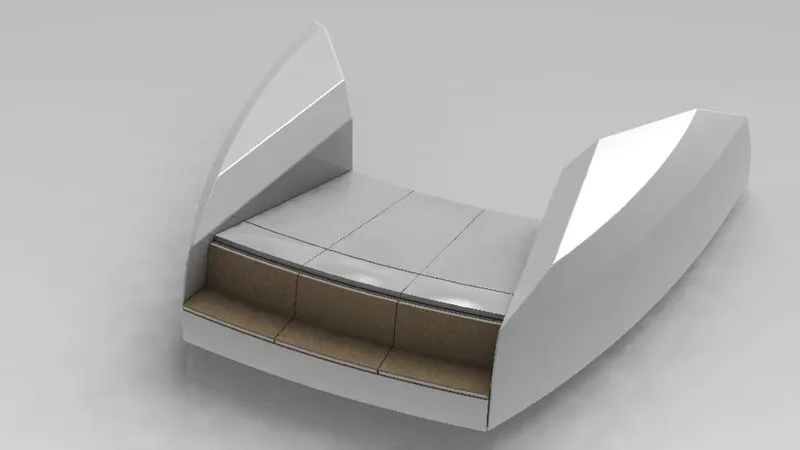
These front middle and rear seats are the accessories of the Yacht for resting and sitting.
In this design the seats are drawn with reference to the deck surface and blueprint which is been imported into the solid works using tools sketch tool and sketch tools & sketch picture.
The seat like appearance is obtained with the help of dome option which again consist of continuous and non continuous option.
Assembly:-
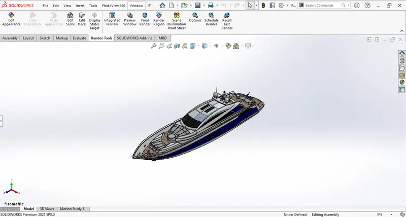
All the components are imported in to the assembly workbench are according to the tree chart and applied mates to fix their position with respect to the fixed body or object.
Rendering:-
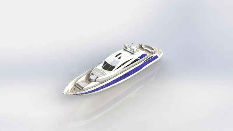
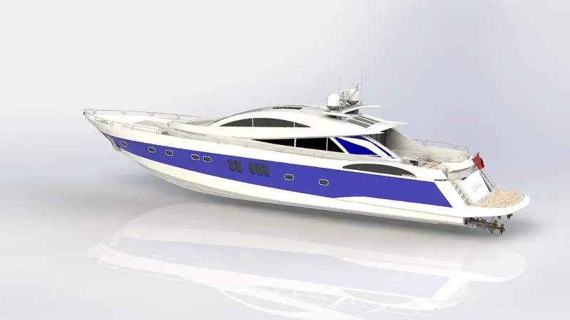
Rendering or image synthesis is the process of generating a photorealistic or non-photorealistic image from a 2D or 3D model by means of a computer program. The resulting image is referred to as the render.
Conclusion:
To conclude, design, assembly and rendering of the Yacht are done using SOLIDWORKS. This project has really helped to enhance the skills in surface modelling and product design. It has given me insight into marine vehicle design and the opportunity to build one. Overall, the project was successful.
THERE ARE PROBLEMS OCCURING IN MY SOLIDWORKS VISUALIZE. RENDERED IMAGES OF YATCH IN SCENES ARE NOT ADDED DUE TO THIS ISSUE. PLEASE APOLOGIZE.