Advanced Sheet Metal Design Using NX Cad Challenge_7_ Metal bracket-II
ADVANCED SHEET METAL DESIGN USING SIEMENS NX CAD - METAL BRACKET-II
OBJECTIVE:
To design a metal bracket and create a draft of it using Siemens NX Sheet metal application.
INTRODUCTION:
Sheet metal is metal formed by an industrial process into thin, flat pieces. Sheet metal is one of the fundamental forms used in metal working, and it can be cut and bent into a variety of shapes. Countless everyday objects are fabricated from sheet metal. Thicknesses can vary significantly; extremely thin sheets are considered foil or leaf, and pieces thicker than 6 mm (0.25 in) are considered plate steel or "structural steel".
Sheet metal is available in flat pieces or coiled strips. The coils are formed by running a continuous sheet of metal through a roll sitter.
NX Sheet Metal: Creating fast, accurate flat patterns is the goal of any organization that manufactures products which contain sheet metal parts. NX Sheet Metal provides a set of tools within the NX design environment that allows for simple and fast design of sheet metal parts, dependent on their material and manufacturing process, the most common of which is straight brake sheet metal forming.
With NX Sheet Metal, formed and unformed representations of the parts are created closely following the industry workflows and best practices for bending calculations, tooling, and sheet metal features. The value lies in improving quality and reducing cost of sheet metal parts by producing an accurate sheet metal pattern as the correct input for part manufacture, whether internally or to a supplier.
DESIGN METHODOLOGY:
Design methodology is explained by the flow chart as follows;
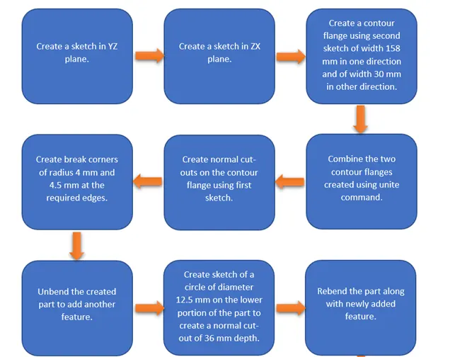
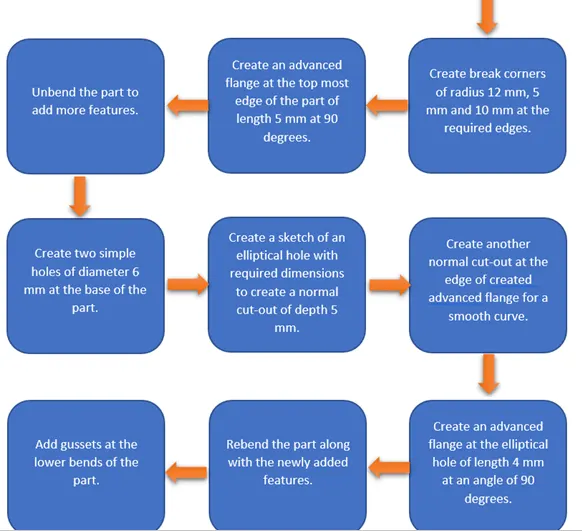
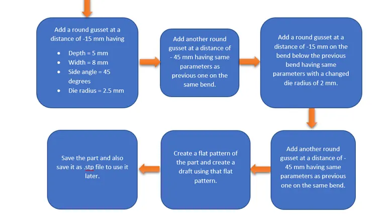
DESCRIPTION:
Sketch:- It is the basic of any design.
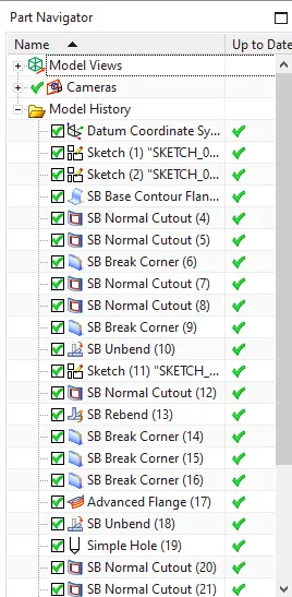
Contour flange:- It creates a base feature by extruding a sketch along a vector, or adds material by sweeping a sketch along an edge or chain of edges. Here two contour flanges are created.
Unite:- It combines the volume of two or more solid bodies into a single body. Here it is used to combine the contour flanges.
Break corner:- It rounds or chamfers a sharp corner of a tab or flange. Here five break corners are created.
Normal cut-out:- It cuts the material by projecting a sketch onto the model and then cutting perpendicular to the faces intersected by the projection. Here seven normal cut-outs are created.
Unbend:- This feature is used to unbend the adjacent bends and flatten them. It is used to create holes and bead.
Rebend:- It is used to rebend the corners that were bent before along with any features added after the unbend feature.
Hole:- It adds a hole to one or more solid bodies in a part or an assembly with options for counterbored, countersunk and threaded. Here one simple hole is created with a diameter of 6 mm.
Advanced flange:- It adds a flange along an edge using a bend angle or a reference face. The edge and reference face can be curved. Here two advanced flanges are created of length 4 mm and 5 mm at an angle of 90 degrees.
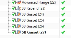
Gusset:- It creates a stiffening gusset on the part. Here four gussets are created on the bends at the lower region of the part.
Flat pattern:- It creates a flat pattern feature from the formed sheet metal part.
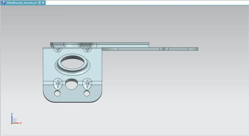
SNAPSHOTS:
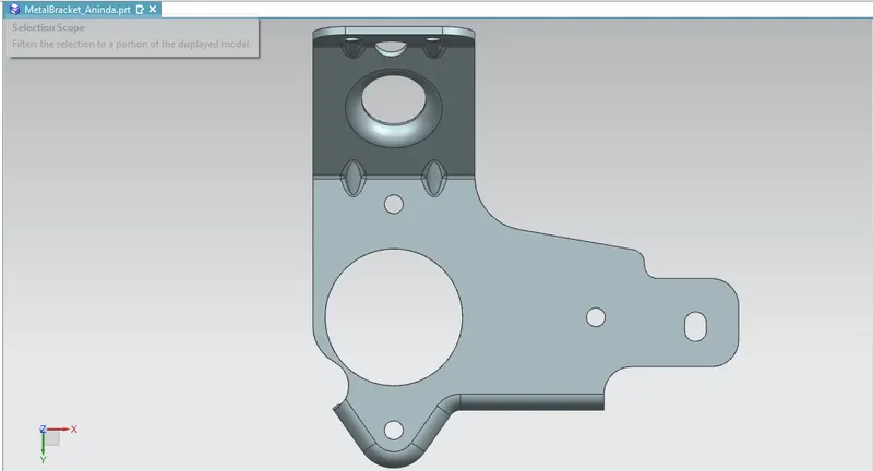
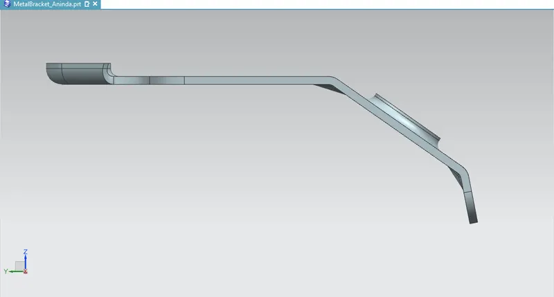
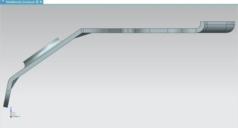
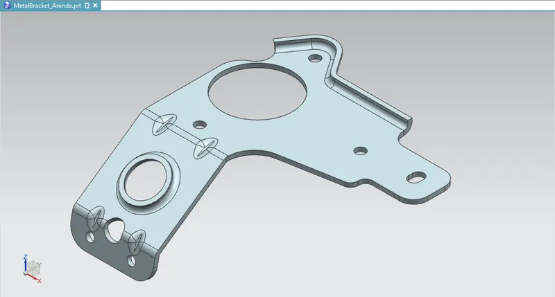
MODEL FEATURE TREE:
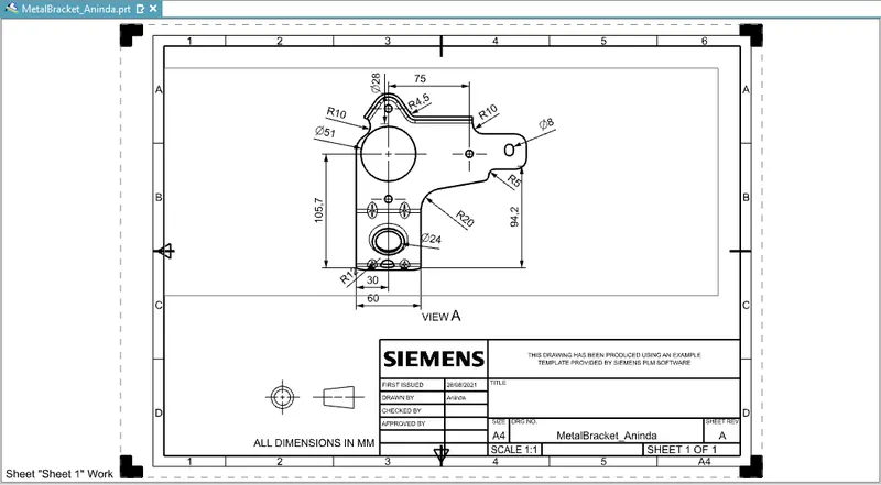
DRAFT (Drawing sheet):
CONCLUSION:
By performing this task, I have learned how to design a metal bracket using features contour flange, unite, rebend, flat pattern, unbend, normal cut-out, break corner, advanced flange, gusset and hole.