Radar Mast & Final Assembly of Yacht
Modelling And Design Of Predator Yatch
Introduction :
This report consists of the detailed report about the design and modelling of the Predator Yatch along with the final rendering of the assembly.
Objective :
The main objective of this report is to give a clear picture about the design of the Predator Yatch starting with the basics and covering almost all the tools required for the modelling in SolidWorks.
The following steps were undertaken for the modelling and Rendering of the Predator Yatch –
- Design of the individual components
- Assembly of the different parts modelled for the Predator Yatch
- Application of the decals, setting up the scene, lights and cameras
- To create a photo-realistic view of the Predator Yatch by rendering of the model using SolidWorks Photo-View 360 and SolidWorks Visualize.
Methodology :
The Predator Yatch Model is made up of the following parts –
- Propeller
- Radar
- Hull
- Garage Door
- Front Seat
- Middle Seat
- Rear Seat
- Superstructure
- Radar Mast
Description Of The Parts And Features Used:
- Propeller:
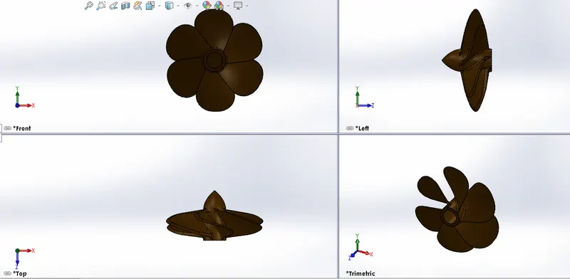
A propeller is a device with a rotating hub and radiating blades that are set at a pitch to form a helical spiral, that, when rotated, performs an action which is similar to Archimedes' screw. It transforms rotational power into linear thrust by acting upon a working fluid, such as water or air.
Features Used-
- Revolve Boss/Base
- Loft Boss/Base
- Fillet
- Cut Extrude
- Circular pattern
Procedure-
- Firstly, open Solid Works and click on new part to start modelling.
- Select the Right Plane in the Feature Manager and start a 2D sketch And Draw the lines and the Spline and add dimensions and relations to fully define the sketch.
- Perform the Boss/Base Revolve operation.
- Now, select the Top Plane in the Feature manager and start a new 2D sketch and draw a 3 point rectangle and add dimensions to fully define it and close the sketch.
- Insert > Reference Geometry > Plane , select the Top plane as first reference and give an offset distance of 360mm then click Ok.
- Select New plane and start a 2D sketch and draw a 3 point rectangle along with the dimensions to Fully define it then close the sketch.
- Now, Insert Boss/Base Loft and select the two sketches to create the Loft and apply fillet of radius 135mm to the edges.
- Create a new sketch on the surface of the axle and draw a circle and add the dimensions.
- Insert Cut Extrude and add a distance of 210mm and make sure the Extruded cut direction is pointed inwards and then add Fillet on the front edge of the loft with a radius of 30mm
- Add another fillet of radius 10mm to the other two base edges connecting to the axle.
- Now, Insert > Pattern/Mirror > Circular Pattern , and select the axle as the pattern axis with a total angle of 360 deg and Number of instances : 6, also select “Equal Spacing” option, select the “Geometry pattern” option and the “Propagate Visual Properties” option too.
- Lastly Click on “Appearances” Button and add color to the Body of the Propeller.
- Radar:
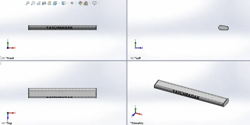
Radar is a detection system that uses radio waves to determine the distance (range), angle, or velocity of objects. It can be used to detect aircraft, ships, spacecraft, guided missiles, motor vehicles, weather formations, and terrain.
FEATURES USED-
- Boss Extrude
- Fillet
- Cut Extrude
- Sketch Pattern
- Mirror
- Split Line
Procedure-
- First, open the SolidWorks. Then, click on the new part to start modelling.
- Select the Right Plane in the Feature Manager and click on 2D sketch and draw the lines and add dimensions to Fully define them.
- Insert > Boss/Base > Extrude , add a depth of 700mm
- Insert a fillet to the edges of the Radar with a radius of 46mm
- Again add a fillet of radius 20mm then with radius of 30mm to the respective edges.
- Now Click on “Offset Entities” on the surface in the right plane and apply a distance of 3mm and make sure that the direction is Outwards.
- Insert > Boss/Base > Extrude , and add a depth of 10mm
- Again select the same surface and click on “Offset Entities” and add a dimension of 10mm and make sure the offset is directed inwards.
- Now draw a circle along with the dimensions and make the previous Offset as “For Construction”.
- Insert > Boss/Base > Extrude, add a depth of 3mm
- Now, insert Fillet with a radius of 3mm to the edge of the extrude created.
- Select the surface and click on 2D sketch icon to make new sketch and draw a polygon and add a dimension of 3.5mm.
- Now insert “Cut Extrude” with a dimension of 1.5mm.
- Now Draw three points on the selected surface as 2D sketch and apply the dimensions.
- Create a sketch driven pattern.
- Apply Fillet to the edges with a radius of 3mm.
- Now Insert Mirror and enable the Merge , Knit and Propagate Visual Properties options.
- Select the Bottom surface and click on 2D sketch and draw a Circle and add the dimension to it.
- Create a Extrude Cut with a depth of 40mm
- Now create a Fillet on the edges of the cut extruded surface with a radius of 3mm.
- Create a new 2D sketch on the Front surface of the radar and draw a Horizontal centerline and add dimensions to it.
- Add a text on the radar by clicking the Tools > Sketch Entities > Text and make the necessary changes.
- Create Split Lines of the Text and select “projection” as the type of sketch and select the faces as the selections.
- Now lastly Change the color of the radar by clicking on the appearance button.
- Hull:
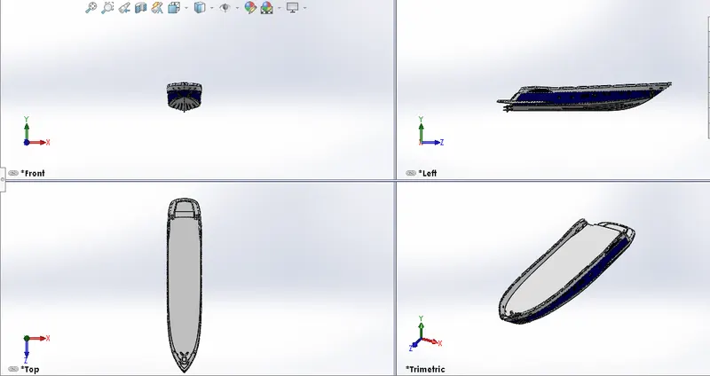
The Hull is the portion of your boat that rides both in and on the top of the water. The boat Hull does not include any masts, sails, machinery or equipment. Here we started the sketch with the help of the Blueprint and used different types of sketch tools & planes are used to create sketches. By using different features & surfaces to complete the hull model and finally we added some decals on the hull for the outer look.
FEATURES USED-
- Surface Loft
- Surface Trim
- Surface Extrude
- Projected Curve
- Surface Knit
- Surface Fill
- Shell
- Cut Extrude
- Boss Extrude
- Chamfer
- Fillet
- Sweep
- Helix/Spiral
- Delete Face
- Revolve Boss/Base
- Linear Pattern
- Mirror
- Split
- Split Line
- Garage Door:
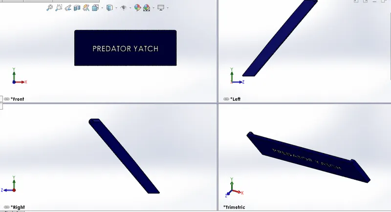
A Garage Door is a large door on a garage that opens either manually or by an electric motor. Garage Doors are generally large enough to accommodate automobiles and other vehicles. Small Garage Doors may be made in a single panel that tilts up and back across the garage ceiling.
FEATURES USED-
- Cut Extrude
- Shell
- Fillet
- Mirror
Procedure-
- First, open the SolidWorks. Then, click on the new part to start modelling and also open the exported body of the Hull as main body: sldprt
- Select the face on the right side of the body and click on 2D sketch and then click to normal view option.
- Draw the lines and add dimensions.
- Insert Cut Extrude and change direction to Through All.
- Now, Insert Shell from the features options and change the distance to 100mm.
- Now, apply fillet on the edge with a radius of 100mm
- Again apply fillet of 15mm radius on the edge then apply a second fillet of the same radius to the opposite edges.
- Click on the 2D sketch option by clicking on the surface on the right plane of the garage door and draw a circle and add dimensions.
- Insert Cut Extrude and change the dimension to 100mm
- Now, Insert a fillet of radius 15mm to the side of the garage door then apply another fillet of radius 10mm to the connected edge.
- Then, apply a fillet of radius 10mm to the upper edge of the garage door.
- Now, Insert a Mirror and select the right plane as the Mirror Face and select the Bodies to mirror option and select the Body of the garage door and enable the Merge, Knit, Propagate visual properties options.
- Now, Create a Reference plane from the reference geometry option and select front plane as the 1st reference and give a offset distance of 31000mm
- Click on the plane created before and click on 2D sketch and draw a centerline and add dimensions to it.
- Create the name of the yatch that is to be written on the Garage Door outer surface.
- Now, Lastly add the Colors to the Garage Door by clicking the Appearance option.
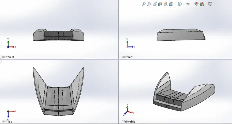
- Front Seat:
With the help of blueprints start sketching for the front seat, here mostly surface options are used to build the model of the Front Seat of the yatch and also we can complete this model within very less time.
FEATURES USED-
- Sketch
- Plane
- Extrude Boss
- Extrude surface
- Surface Trim
- Surface Loft
- Cut Extrude
- Fillet
- Appearance
- Middle Seat:
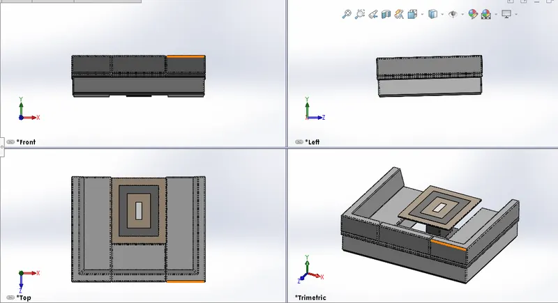
Top view of the blue print is used to place the Middle Seat of the yatch same as the Front Seat, the Middle Seat is also created with the help of surface options and also add Decals on the table for a better look.
FEATURES USED-
- Sketch
- Plane
- Extrude Boss
- Cut Extrude
- Fillet
- Appearance
- Rear Seat:
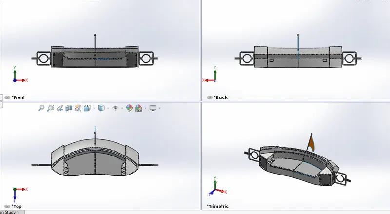
Followed the same steps as followed in front seat & Middle seat, this gave more interesting factors to create models (eg: flag) and learned new methods for sketching & modelling.
FEATURES USED-
- Sketch
- Plane
- Extrude Boss
- Extrude Surface
- Surface Loft
- Cut Extrude
- Fillet
- Appearance
- SuperStructure:
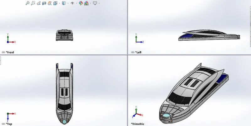
Firstly we started the sketch with the help of hull surface & blueprint. Then traced a few areas for reference from the blueprint, then we sketched all sketches by using different sketch tools & planes and modelled the whole structure by using different features & surfaces.
FEATURES USED-
- Sketch
- Plane
- Extrude Boss
- Extrude Surface
- Surface Loft
- Trim
- Surface Trim
- Sweep
- Split
- Cut Extrude
- Fill
- Fillet
- Dynamic Mirror
- Appearance
- Radar Mast:
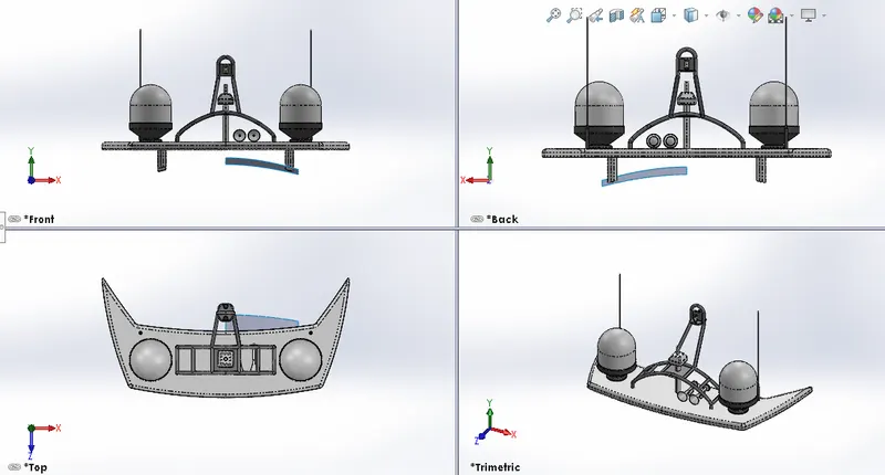
At first start the sketch with the help of superstructure surface & blueprint, here we used a variety of Sketch tools & Feature tools to create the RadarMast model.
FEATURES USED-
- Sketch
- Plane
- Extrude Boss
- Fillet
- Revolve
- Sweep
- Mirror
- Projected Curve
- Chamfer
- Dome
- Assembly And Rendering:
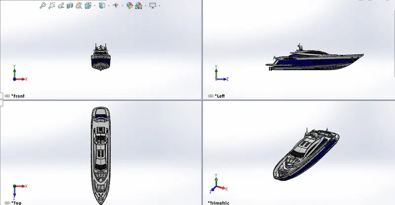
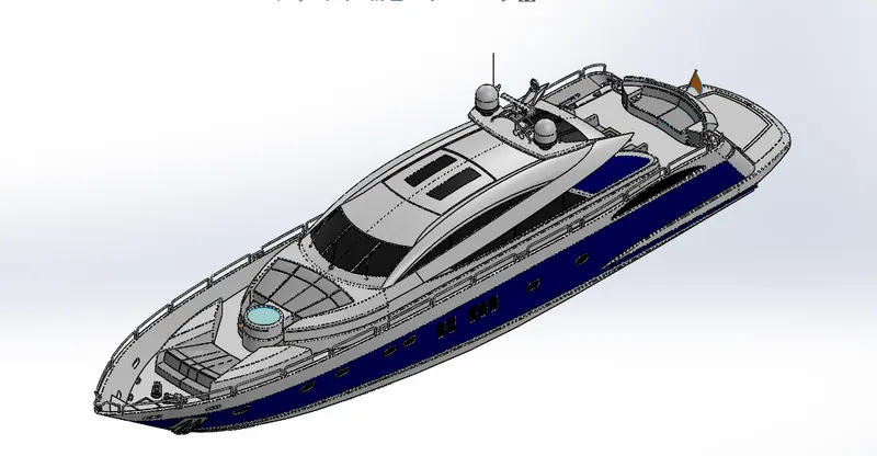
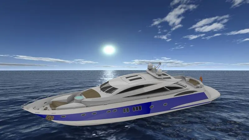
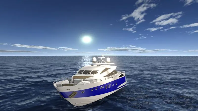
After creating all the parts we then started to assemble, all the parts one by one and gave suitable relations by using mate options in the assembly.
CONCLUSION:
- By the above parts & assembly files , Learned more information & Design thinking approach is been increased while modelling. The parts are inserted into the assembly environment and by applying the mates the Yatch is assembled.
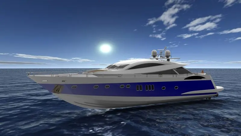
- The realistic image was rendered with the use of the ‘Photoview 360 & SolidWorks Visualize’.