Photo Realistic Rendering
Modelling And Design Of An American Chopper
Introduction :
This report consists of the detailed report about the design and modelling of the American Chopper along with the final rendering of the assembly.
Objective :
The main objective of this report is to give a clear picture about the design of the American Chopper starting with the basics and covering almost all the tools required for the modelling in SolidWorks.
The following steps were undertaken for the modelling and Rendering of the American Chopper –
- Design of the individual components
- Assembly of the different parts modelled for the American Chopper
- Application of the decals, setting up the scene, lights and cameras
- To create a photo-realistic view of the American Chopper by rendering of the model using SolidWorks Photo-View 360 and SolidWorks Visualize.
Methodology :
The American Chopper Model is made up of the following parts –
- Transmission Belt
- Kickstand
- Chain
- Rear fender
- Rear Wheel
- Peddle
- Front fender
- Front wheel
- Oil tank
- Front fork
- Chassis
- Engine
- Fuel tank
Description Of The Parts And Features Used:
- Transmission Belt:
It is used to transmit power between two shafts. Belts may be used as a source of motion, to transmit power efficiently or to track relative movement.
FEATURES USED-
- Boss extrude
- Fillet
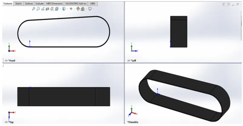
Procedure-
- Firstly, open SolidWorks and click on new part to start modelling
- Before creating the sketch change the plane names.
- Front Plane- FrontPlane Transmission Belt
- Top Plane- TopPlane Transmission Belt
- Right Plane- RightPlane Transmission Belt
- Then select the FrontPlane to start the sketch.
- The 2D sketch is created in the front plane by giving it dimensions, relations to fully define a sketch. While sketching, the offset command is used to duplicate the sketch t some distance.
- After this process, the sketch is closed. Then, the extrude command is used to convert a 2D sketch into a 3D model.
- Then, the fillet is applied to the belt as per the requirements, the model of transmission belt is created.
- The model is saved with the name of Transmission Belt.
- Kick Stand:
A kickstand is a device on a motorcycle that allows the bike to be kept upright without leaning against another object or the aid of a person. A kickstand is usually a piece of metal that flips down from the frame and makes contact with the ground. It is generally located in the middle of the bike or towards the rear.
FEATURES USED-
- Cut Extrude.
- Boss Extrude.
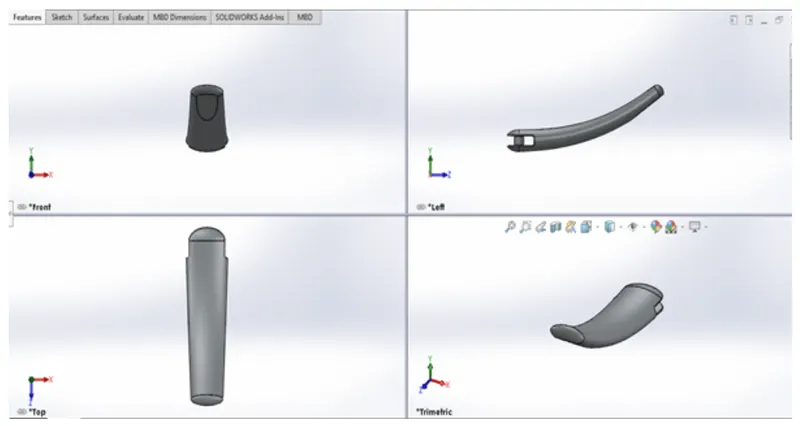
Procedure-
- First, open the SolidWorks. Then, click on the new part to start modelling.
- Before creating the sketch change the names of the planes.
- Front Plane – FrontPlane
- Top Plane – TopPlane
- Right Plane – MidPlane
- Then, the mid-plane is selected to start the sketch.
- The 2D sketch is created in front plane by giving it dimensions, relations to fully define a sketch. While sketching we used the spline and trim commands.
- There are two new planes created and ellipse are drawn in the new plane as per the requirement.
- Then the loft command is used to create a loft for the KickStand.
- The extrude cut command is used to cut the parts which are not required for the stand.
- Front Fender:
Fender is the American English term for the part of an automobile, motorcycle or other vehicle body that frames a wheel well (the fender underside). Its primary purpose is to prevent sand, mud, rocks, liquids, and other road spray from being thrown into the air by the rotating tire.
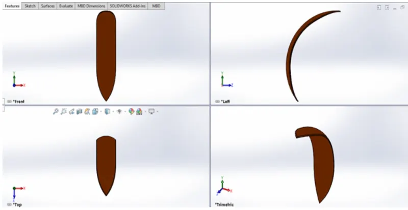
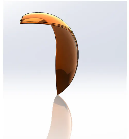
FEATURES USED-
- Sketch
- Offset Entities
- Trim Entities
- Revolve
- Dynamic Mirror
- Split
- Appearance
- Rear Fender:
Fender is the American English term for the part of an automobile, motorcycle or other vehicle body that frames a wheel well (the fender underside). Its primary purpose is to prevent sand, mud, rocks, liquids, and other road spray from being thrown into the air by the rotating tire.
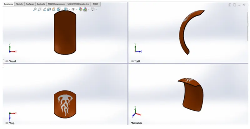
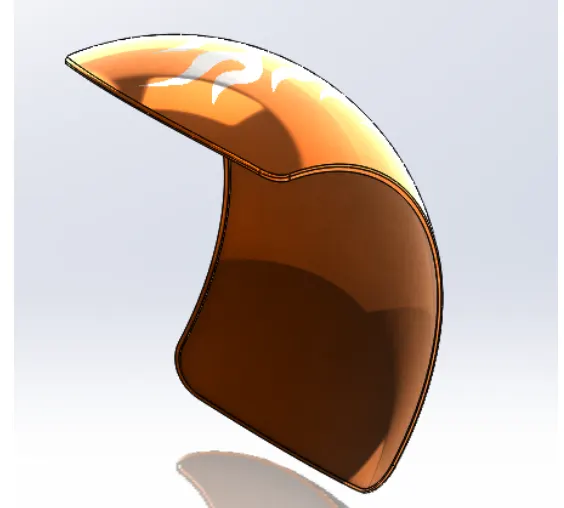
FEATURES USED-
- Revolved Boss
- Split
- Fillet
- Shell
- Chain:
The chain on the bike, is responsible for transferring the mechanical power from the engine to the rear wheel of the bike.
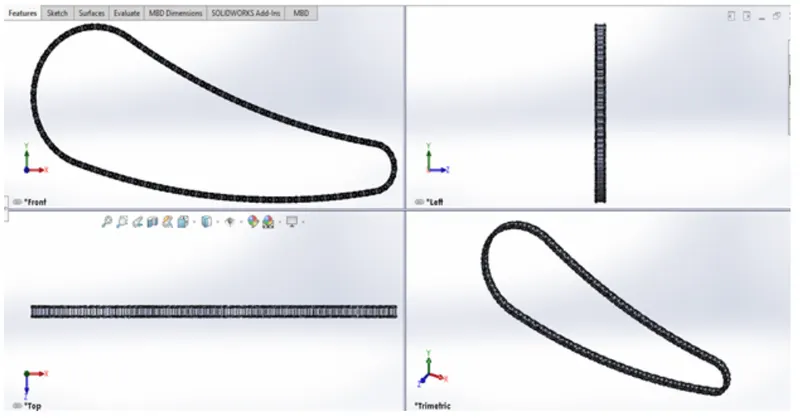
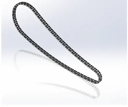
FEATURES USED-
- Extruded Boss
- Fillet
- Projected Curves
- Curve Pattern
- Mirror
- Appearance
Blocks:
We can make, save, edit, and insert blocks for drawing items and sketch entities that we use often, such as standard notes, title blocks, labels positions, and many more. We can attach blocks to geometry or drawing views, and we can insert them into sheet formats.
To Create Blocks:
- Create a Sketch.
- Click make (Blocks Toolbar) or Tools > Block > make ….
- Select the sketch entities you want to make as a block for block entities.
- Repeat steps 2-4 for each of the remaining sketch entities.
- With the sketch in edit mode, add the necessary relations.
- Save the part.
Patterns:
The curve Driven Pattern tool allows us to create patterns along a planar or 3D curve. We can base our pattern on an open curve, or a closed curve, like a circle. In the chain part Curve Driven Pattern is used.
- Oil Tank:
The Oil-Tank is another part of the chopper. Oil tank is used to store the oil required to run the engine. Oil tank is the hollow one. The thickness of the oil tank is given as 3mm in our chopper.
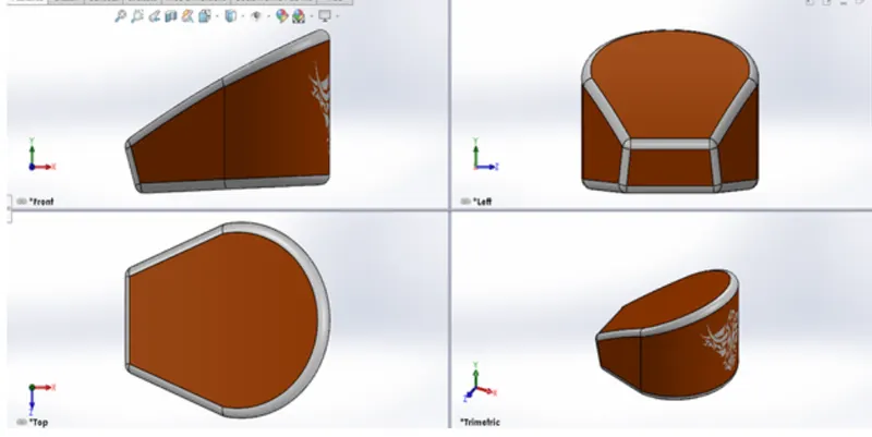
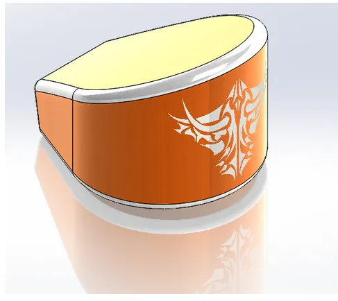
FEATURES USED:
- Extruded Boss
- Fillet
- Shell
- Combine
- Pedal:
Pedal is the external part attached to the chassis. The pedal is used to rest the leg on top of that. For the comfort of the rider pedal is used.
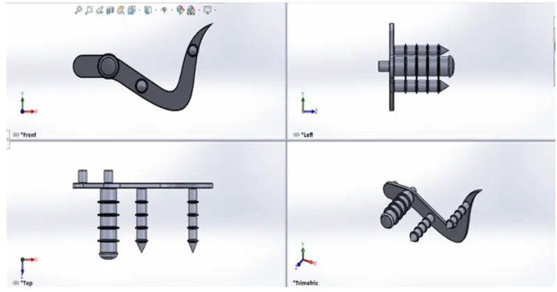
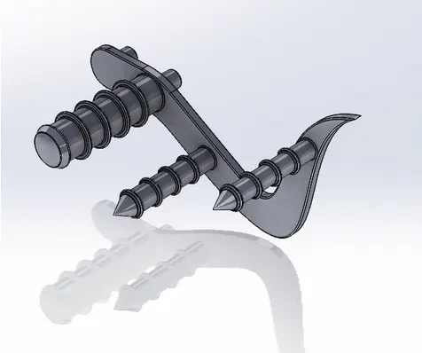
FEATURES USED-
- Sketch
- Extrude
- Fillet
- Linear Pattern
- Dome
- Chamfer
- Appearances
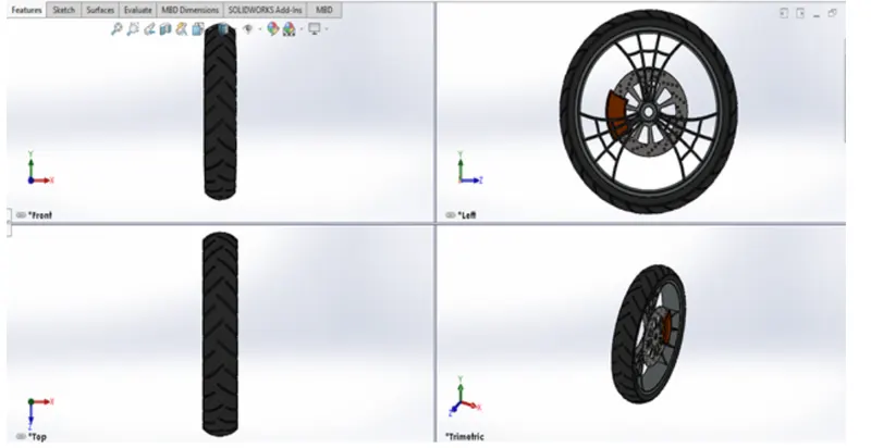
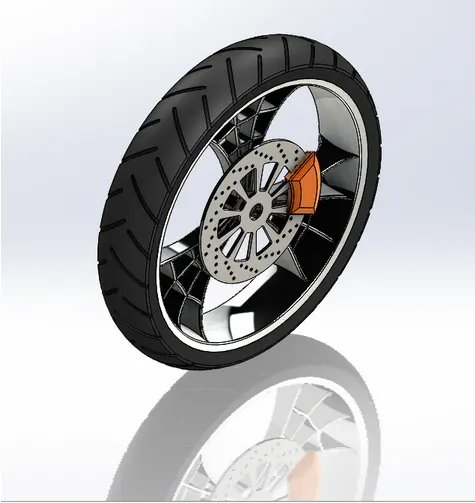
- Front Wheel:
A wheel is a circular block made of the Steel/Alloy material. On the top of the wheel, the tire is attached. The Tire is made of rubber top of the wheel, the tire is attached. The tire is made of Rubber and it has thin within it. Wheel rotates to move the vehicle.
FEATURES USED-
- Extruded Boss
- Cut Extrude
- Revolve Cut
- Circular Pattern
- Combine
- Fillet
- Chamfer
- Appearance
Circular Pattern:
Circular pattern is used to create a pattern of the spokes and the patterns (Grooves) available in the tire. Also, it is used to create holes in the brake discs of the front wheel. The parent bodies/features are used to create a different number of instances required to create the pattern circularly.
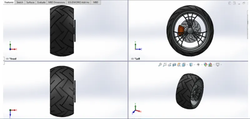
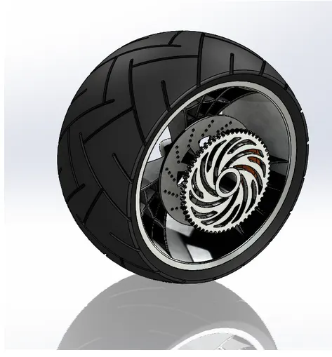
- Rear Wheel:
A wheel is a circular block of a hard and durable material where the center has been bored with a circular hole through an axle bearing which the wheel rotates.
FEATURES USED-
- Sketch
- Revolve
- Trim
- Fillet Entities
- Boss/Base Extrude
- Planes
- Revolve Cut
- Linear pattern
- Chamfer
- Fillet Features
- Cut Extrude
- Circular Pattern
- Appearances
- Front Fork:
Most motorcycles today use telescopic forks for the front suspension. The forks can be most easily understood as simply large hydraulic shock absorbers with internal coil springs. They allow the front wheel to react to imperfections in the road while isolating the rest of the motorcycle from that motion. It filters the bums to give comfort to the rider.
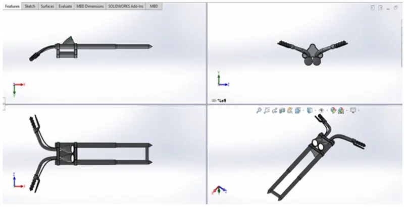
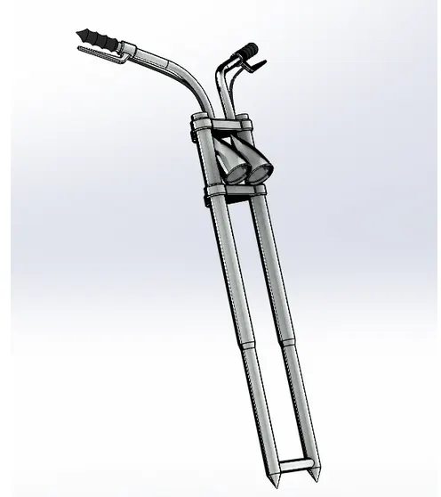
FEATURES USED-
- Extruded Boss
- Revolved Boss
- Fillet
- Extrude Cut
- Dome
- Revolved Cut
- Swept Boss
- Project Curve
- Mirror
- Combine
- Chassis:
The chassis or Frame forms its skeleton. All the components of a motorcycle, like the suspension, wheels, fuel tank, seats, handlebars etc. Are attached to this base structure which lends a motorcycle its strength and ability to handle well.
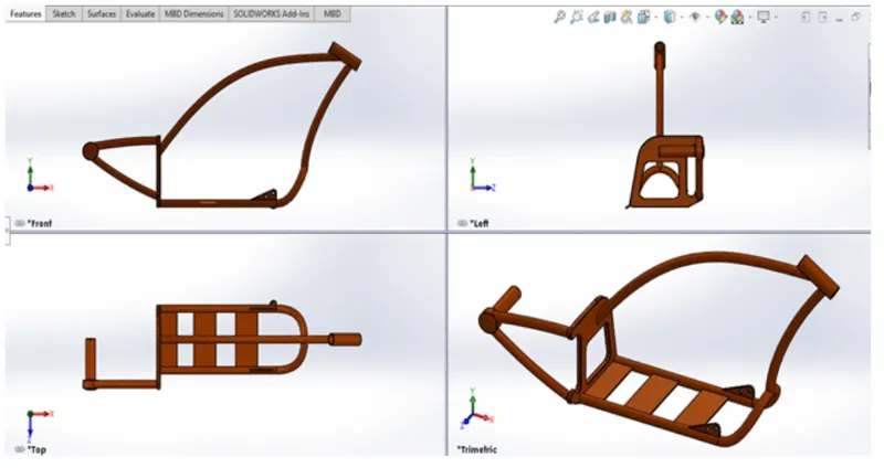
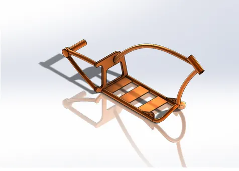
FEATURES USED-
- Sketch
- Offset
- Convert entities
- Project Curve
- Trim
- Plane
- Split
- Revolve
- Cut Extrude
- Fillet
- Combine
- Appearance
- Engine:
An Engine is the Prime mover for the Bike. The engine converts a chemical energy into the heat energy and then the heat energy is converted into mechanical work.
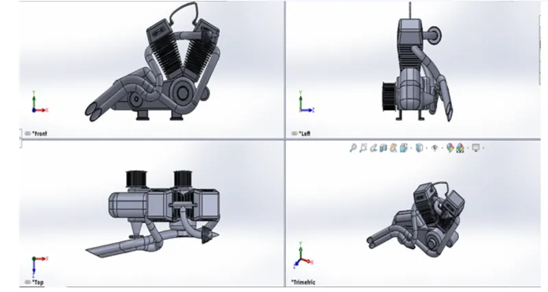
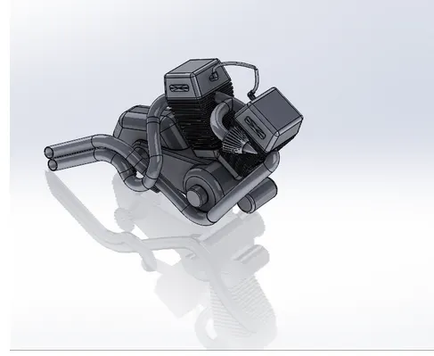
FEATURES USED-
- Sketch
- Convert entities
- Trim
- Revolve
- Boss extrude
- Cut extrude
- Offset
- Dome
- Fillet
- Projected curve
- Composite curve
- Sweep
- Mirror
- Circular pattern
- Split
- Gas Tank:
A gas tank (Petrol tank) is a safe container for inflammable fluids. Through any storage tank for fuel may be so called, the term is typically applied to part of an engine system in which the fuel is stored and propelled (fuel pump) or released (Pressurized gas) into an engine.
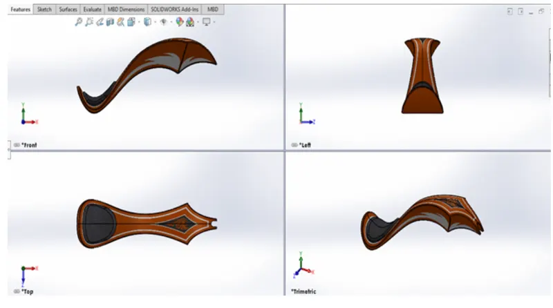
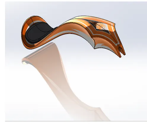
FEATURES USED-
- Sketch
- Trim
- Projected Curve
- Convert entities
- Sweep Surface
- Loft Surface
- Fill Surface
- Surface trim
- Surface knit
- Sweep cut
- Fillet
- Appearances
Assembly Of American Chopper:
- MAIN ASSEMBLY-
Initially, the Chassis part is inserted in the assembly by using insert parts in the option. After that the part is inserted in the assembly environment and clicked ok fix the chassis. After that, the other parts of the chopper are inserted into the assembly and given possible mate conditions.
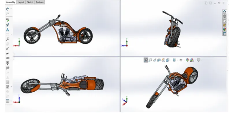
FEATURES USED TO ASSEMBLE AMERICAN CHOPPER-
- Mates
- Insert part
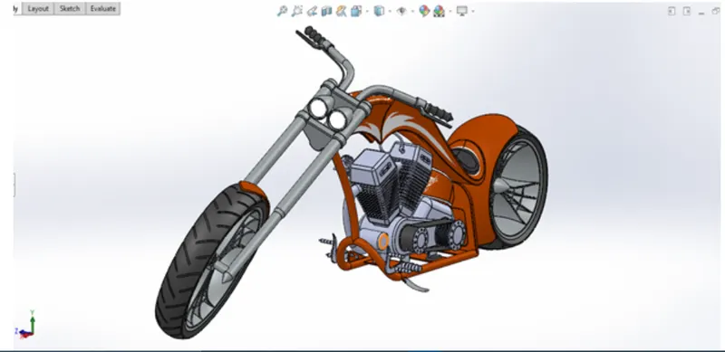
Mates:
Mates create geometric relationships between assembly components. As we add mates, we define the allowable directions of linear or rotational motion of the components. We can move a component within its degrees of freedom, visualizing the assembly’s behaviour.
Rendering:
- Rendering is the process of creating realistic images of the photorealistic model with the environment.
- Rendering has been done in two ways in SolidWorks. The following are the two ways:
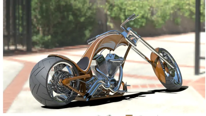
1.Photoview 360
2.SolidWorks Visualize
- In the photorealistic model, some of the mate conditions and positions are changed to render realistic models.
- Then the photorealistic model is rendered into images with different views.
CONCLUSION:
- The parts of the chopper are sketched and modelled in the SolidWorks.
- The parts are inserted into the assembly environment and by applying the mates chopper is assembled.
- The realistic image was rendered with the use of the ‘Photoview 360 & SolidWorks Visualize’.
- I would like to thank my mentor Mr. Soundar Rajan for helping me with the challenges I faced while modelling this beautiful beast.
SolidWorks Chopper Design&Model ReportAninda
American Chopper Assembly Aninda