Advanced Sheet Metal Design Using NX Cad Challenge_1_Casing Design
CASING DESIGN USING NXCAD
Objective-
The main objective of this report is to give a clear picture about the design of the Casing Design starting with the basics and covering almost all the tools required for the modelling in NX CAD.
Introduction-
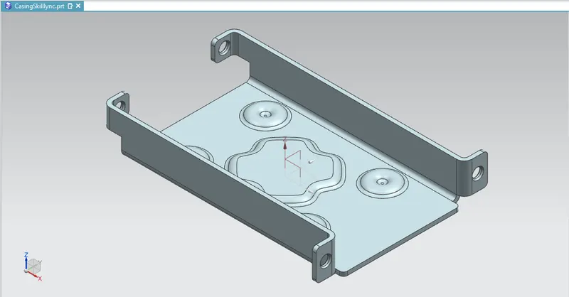
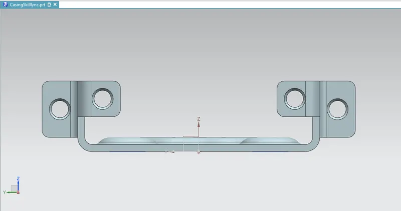
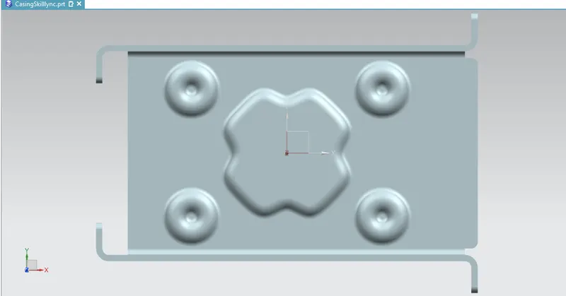
This report consists of the detailed report about the Sketching and modelling of the Casing Design along with the draft of the respective sheet metal design.
Approach-
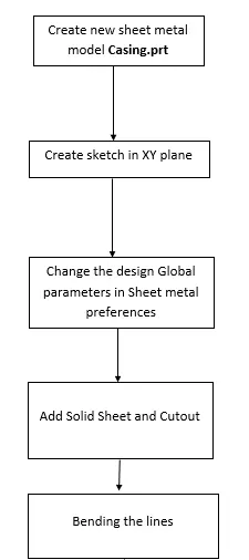
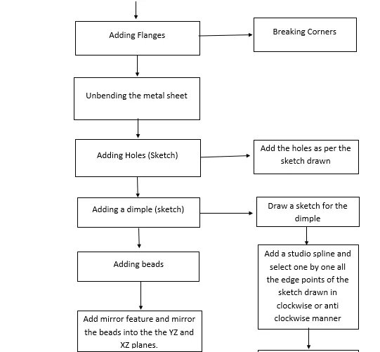
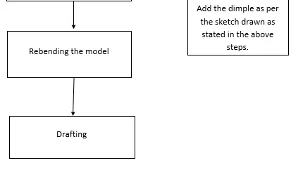
Tools/Features Used-
- Tab: This command is used to create a base feature by extruding a sketch along a vector by a thickness value or by adding material to existing faces and bend regions of a sheet metal.
- Flange: This feature is used to add a flat flange at an angle to a planar face and add a bend between the two, it consists of two regions 1. Bend Region, 2. Web.
- Normal Cutout: This command is used to cut a material by projecting a sketch onto the model and then cutting perpendicular to the faces intersected by the projection.
- Bending: This command is used for the bending of the created sheet metal model using proper fillet & bending radius.
- Breaking Corners: This command is used to round or chamfer sharp corners of a tab or flange.
- Unbend: This feature is used to unbent the sheet metal taking any one face as a stationary face.
- Holes: This feature is used to create a hole in the desired position in the model as per the sketch drawn.
- Punch/Dimple: This command is used to lift an area of the model inside a sketch that simulates a stamping tool.
- Beads: This feature is used to lift material along the contour of a sketch that simulates a stamping tool.
- Rebending: This command helps to rebend the unbend command of the sheet metal after it is used when needed.
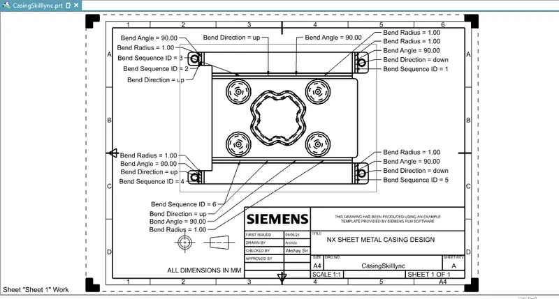
- FlatPattern/Drafting: This feature is used to create a flat representation of a formed sheet metal part, the flattened version of the part is associative to the formed version this command is used to create a 2D representation of a 3D sheet metal part.
Snapshots-
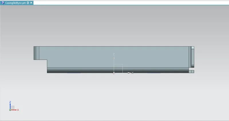
Detailed Drawing Sheet-
Conclusion-
- The parts of the chopper are sketched and modelled in the NX CAD.
- Learned about the sheet metal design and modelling.
- Learned about the various Tools/Features used to create this model.
- Did the Drafting of the sheet metal model.