Advanced Sheet Metal Design Using NX Cad Challenge_7_ Metal bracket-II
SHEET METAL DESIGN OF METAL BRACKET II USING NX-CAD
OBJECTIVE:
To learn the Sheet Metal design process and to design a Sheet Metal bracket II in parametric CAD software Siemens NX following industrial workflow.
INTRODUCTION:
Sheet Metal is a metal with a small thickness ranging from 0.5-6mm which is made thin and flat by rolling or hammering process. A number of mechanical components are made up of Sheet Metal. Sheet metal is widely used in the manufacturing industry for making numerous daily used products due to its various advantages.
In Sheet Metal, a constant called K factor rules the bend parameters of all the bends in the part. It is the ratio of the length of the neutral axis to the thickness of the sheet metal.
In this project, a bracket is designed in Siemens NX CAD software following the industrial approach. The use of a parametric modelling environment is the main use made in this project. This project focuses on the stiffening process of a bracket with the application of advanced flanges. All the sheet metal design considerations are carefully considered while doing this proje
DESIGN METHODOLOGY:
The bracket designed for this project consists of features like contour flange, normal cut-outs, advanced flanges, and holes. Every feature is designed in an order following the industrial procedure to keep the design intent. The design methodology used for this project can be summarized as depicted in the flowchart below
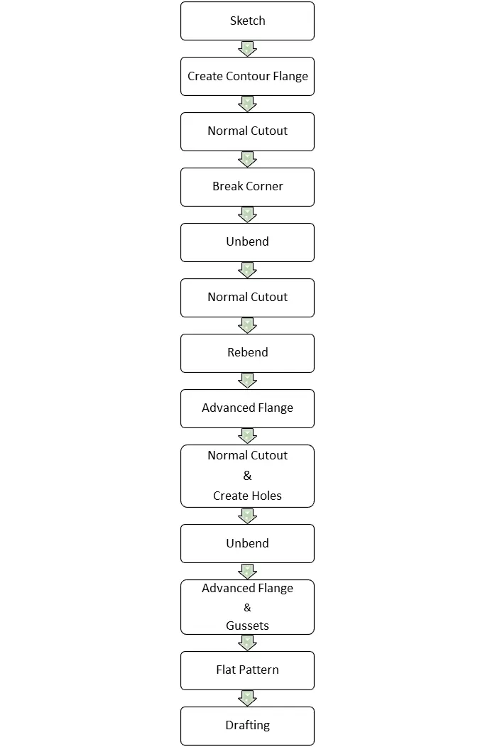
TOOLS AND FEATURES USED ON SHEETMETAL TO DESIGN BOX ASSEMBLY:
- Sketch
- Contour Flange
- Normal cutout
- Break corner
- Unbend
- Hole
- Advanced flange
- Re-bend
- Gussets
- Flat pattern
TOOL AND FEATURE DESCRIPTION:
- SKETCH
It is a 2d representation of a 3d part. It includes entities like line, rectangle, spline, circle, etc. It is a predetermined drawing with dimensions and relations.
- CONTOUR FLANGE
It is created with one or more edges at specified location. The minimum flange length must be at least four times the thickness of the sheet metal. Bend radius is equal to the sheet metal thickness.
3. NORMAL CUTOUT
This command is to remove the desired shape of material. Removal sketch can be drawn on the sheet metal face, wherever required.
4. BREAK CORNER
This command gives a smooth finish over the corners of the sheet metal part.
5. UNBEND
It makes the part unbend, that is all the features done are made flat. This is useful while sketching on the corners and bend areas.
6. HOLE
This feature makes required type of hole like general, drill, screw clearance, threaded and series of holes.
7. ADVANCED FLANGE
This feature adds flange along the curves at specified reference and angle.
8. REBEND
This command puts back all the bends already created also along with new features included while in unbent state.
9.Gussets
Gussets are basically supporting features that provide the structure of the part of the product form the base tab or flange wherever the bend exists.
10.Flat Pattern
Flat pattern is the representation of the entire sheet metal component in the 2D form of the flat sheet metal with all the bends, cut-outs, holes, and additional features in the form of lines or edges.
STANDARD VIEWS:
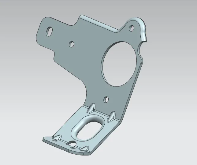
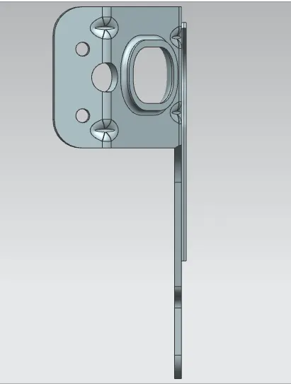
ISOMETRIC VIEW
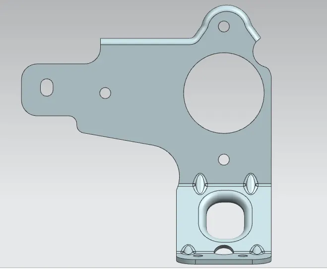
LEFT VIEW
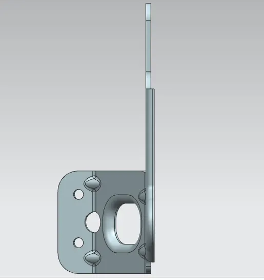
TOP VIEW
BOTTOM VIEW
DRAFTING(Drawing Sheet):
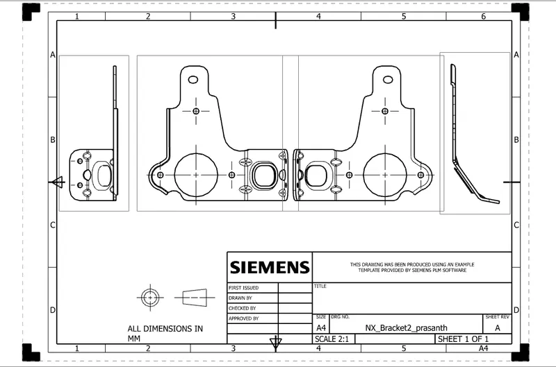
After the design is complete, the execution or the manufacturing of the component requires a technical drawing of the component with the provided scale and with accuracy. The necessary details such as annotations, callouts, bend tables can be added as per the requirement. For this bracket design project, a drawing is created out of the flat pattern in a 1:1 scale in an A3 sheet, and an additional drawing showing different views is also shown.
CONCLUSION:
In this project, a Sheet Metal bracket is successfully designed from a solid body in the sheet metal workbench of Siemens NX. The advantage of a parametric modelling environment is used to maintain our desired design intent and all the necessary features are applied in order following the industrial workflow.