Radar Mast & Final Assembly of Yacht
MODELING OF SUNSEEKER PREDATOR 108 YACHT SOLIDWORKS
Objectives-
The key objectives of this project are as follows:-
- To learn and understand the plethora of basic and advanced tools and / features available for creation of parts and assembly models in SOLIDWORKS
- To learn complex surfacing features in SOLIDWORKS.
- To assemble the different parts modeled in the yacht assembly.
- Application of decals, setting up the scenes, cameras, perspective and lights, etc.
- To render and make the realistic view of the yacht in the SOLIDWORKS Visualize software.
Introduction-
Any product developed in an industry comes out from the mind of a designer through the design, simulation, manufacturing and testing process. This report contains a detailed part modelling, assembly, final rendering of a custom designed sunseeker predator yacht in SOLIDWORKS as a CAD tool. This is a 108 feet long real-sized yacht. Part modelling in general means to create a virtual prototype of a part. It can be used for various purposes. In part modelling, we first sketch the part/ component and create the 3D part using different features. Each part of assembly can be modelled separately and they can be assembled together with application of mates in assembly.
Design Methodology-
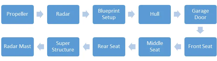
The following flowchart depicts the sequence of part modelling and assembly for sunseeker predator yatch in SOLIDWORKS:
Details of SOLIDWORKS Features Used -
Sketch
The sketch is used to create the 2D representation of model. In solid work there are different entities are available like as follows:
- Line
- Circle
- Arc
- Spline
- Rectangle
- Polygon
- Fillet
- Ellipse
(Some sketch entities like line, circle, spline, arc, rectangle, etc. contain more options)
- Offset
The offset command create parallel line, curve, and concentric circles through a point or at a specified distance.
- Trim and extend entity
The trim command is used to remove the selected extra line/parts of an object. And the extend command is used to extend the selected boundaries or edges.
- Covert entity
It is used to project the last sketch in to the current sketch plane.
- Mirror
Mirror is used to create remaining half of a sketch/ copy of selected sketch about a specified line.
- Linear sketch pattern
It is used to create multiple instance of feature that can uniformly specified along one or two linear paths.
- Smart dimension
It allows you to dimension the part which is created.
- Dynamic mirror
Select the dynamic mirror feature to mirror pre-existing sketch. First select line, centerline, and linear model edge about which to mirror, and then create a sketch to mirror.
Path - Tool> Sketch Tools>Dynamic Mirror
Extruded Boss/Base:-
It is used to convert 2D sketch into 3D model in one or both directions from sketch plane. Here you have to specify direction up to surface, vertex, value, body from sketch plane.
Extrude cut
It helps to remove material from the created 3D model by using 2D sketch. It is opposite of extrude boss/bass feature. Here also you have to specify direction up to surface, vertex, value, body from sketch plane.
Revolved Boss/Base:
It is used to revolve a 2D sketch (one or more profile) along a axis, line or centerline.
Revolved cut:
This feature is just opposite of revolve boss/base. The revolved cut allows to cut a profile around an axis, plane, and line to create complex geometry.
Swept Boss/Base
A swept feature is used to create a solid body by moving a closed entity/ profile along specified sketch/path. In order to complete a feature, two sketches are necessary. One will be the closed profile and second will be the path.
Swept Cut
A swept cut feature allows to cut a 3D model by sweeping a closed sketch profile along a specified path sketch. The path sketch will control the direction of cut. Profile sketch should be connected to the path sketch.
Lofted Boss/Base
The loft feature creates a solid body by making transition between multiple profile and guide curve. It helps to generate complex geometry in one feature.
Lofted cut
The loft cut is allows to remove material between two sketch profiles. Make sure that selections are must under the profile selection box and not the guide curve selection box
Fillet
It is used to create a rounded shapes at internally or externally faces of the part. There are different types of fillet:
- Constant Size fillet
- Multiple radius fillet
- Round corner fillet
- Setback fillet
- Variable size fillet
- Face fillet
- Full round fillet
- Asymmetric fillet
Chamfer
This feature is creates a cut on selected edge, face or a vertex. Types of chamfer:-
- Angle –Distance- Enter the values of distance and angle in the chamfer parameter box.
- Distance- Distance- Enter the values for both distances in the chamfer parameter box or on the side of selected edges.
- A vertex- Enter values for the three distances on each side of selected vertex.
Patterns
- Linear pattern – To create multiple instances of one or more feature to that can space uniformly along specified path, plane.
- Circular pattern – To create multiple instances of one or more feature to that can space uniformly along an axis, line.
- Curve Driven Pattern – To Curve creates multiple instance of one or more feature to that can space uniformly along 3D curve (open or closed curve).
- Sketch Pattern- Using sketch points within a sketch, we can specify a feature pattern. The seed feature propagates throughout the pattern to each point in the sketch. This can use sketch driven patterns for holes or other feature instances.
Shell
It is used to define the thickness of wall, hollows out a part, leaves open the selected faces. Shell may be with uniform or multiple thickness faces.
Dome
Dome features is used to one or more dome on the same model in one feature.
- Face to dome - Used to apply dome to faces whose centroid lies outside the face.
- Elliptical Dome -Used to apply dome for cylindrical/ conical model.
Path- Insert>Feature>Dome
Split
Split feature is used to create multiple body or surfaces from one part/ surface. In the trim tool box we need to select sketch and click on cut part. In this feature we can create multiple body or consume cut bodies.
Path- Insert>Feature>Split
Combine
There are three different options are available to use combine feature.
- Add-To merge multiple bodies together into one.
- Subtract-To remove multiple bodies from main body.
- Common- To add two bodies together and keep the area that is common to them.
Path- Insert>Feature>Combine
Feature description for surface Modelling:
Surface modelling is used to build out a represent of solid objects exterior and it’s a contours. In this project, most of the parts are designed as surface model at first. A surface is designed accurately and solid body is created out of the surface model one the knitting of surface is successfully done.
Following feature are used in design parts of yacht.
Swept Surface
The surface is created by sweep profile and sweep path.
Lofted Surface
The surfaces are generated by multiple 3D curves / existing edges. There should be a tangency between the selected curve/edges.
Boundary Surface
The boundary surface creates surfaces that can be tangent or curvature continuous in both direction. In most of cases, we get high quality result as compare to lofted surface.
Filled Surface
The feature create a surface to fill the gap in a model.
Surface Trim
It is used to cut away material from a surface.
Extend Surface
This feature extend the surface by selecting as edge, multiple edges or a face.
Surface Knit
The surface knit feature combine multiple faces and surfaces into one. Surface edges must be adjacent and not overlapping.
Offset Surface
The Offset Surface tool creates a new surface body from an existing set of faces. The faces may be solid or surface faces
Delete Face
You can delete faces from surface and solid bodies.
Path- Surface> Insert> Face> Delete
Appearance
An appearance is define the visual properties of model which include color and texture. We can apply appearance to the individually to the complete model / one or more face /edges .It does not affect on physical property which are defined by material.
There are four ways to apply appearance-
- Surface Color- Provides one or more multiple specific surfaces with a color by clicking on the “Face” option.
- Feature Color- Provides one or more multiple specific features with a color by clicking on the “Feature Name” option.
- Body Color- Provides one or more multiple specific bodies with a color by clicking on the “Body” option.
- Part Color- Provides a complete part with a color by clicking on the “Part Name” option.
Description of sunseeker predator yacht parts and used features in detailed:-
- Propeller
The traditional agent employed to move a ship is a propeller, sometimes two and, in very rare cases, more than two. The necessary propeller thrust T required to move the ship at speed V is normally greater than the pertaining towing resistance RT, and the flow related reasons are, amongst other reasons.
Basic Nomenclature used to describe propeller geometry:
Hub: The hub of a propeller is the solid center disk that mates with the propeller shaft and to which the blades are attached. Ideally the hub should be as small in diameter as possible to obtain maximum thrust, however there is a tradeoff between size and strength. Too small a hub ultimately will not be strong enough.
Blade Root and Blade Tip: The root of a propeller blade is where the blade attaches to the hub. The tip is the outermost edge of the blade at a point furthest from the propeller shaft.
Blade Face and Back: The face of a blade is considered to be the high-pressure side, or pressure face of the blade. This is the side that faces aft (backwards) and pushes the water when the vessel is in forward motion. The back of the blade is the low pressure side or the suction face of the blade. This is the side that faces upstream or towards the front of the vessel.
Leading and Trailing Edges: The leading edge of a propeller blade or any foil is the side that cuts through the fluid. The trailing edge is the downstream edge of the foil.
Features used to create Propeller:
- Rename the Planes:-
Front Plane – Front Plane of Propeller
Top Plane- Top Plane of Propeller
Right Plane-Mid Plane of Propeller
- Sketch
- Revolve Boss/Base
- Reference Geometry/ New Plane Create
- Lofted Boss/Base
- Fillet
- Cut Extrude
- Circular Pattern
- Appearance: - Custom Brown, RGB No. 71,45,0 Resp.
- Save the part- Propeller
Note- All used features are explained above.
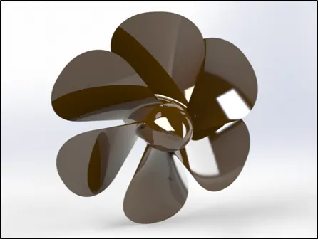
Fig.1 Propeller
2. Radar
Yacht/ Marine Radio Detection and Ranging is used to detect project and their position relative to yacht current location. Radar is a vital navigation component for safety at sea and near the shore. It works by sending out a radio signals. When the signals hits an object, it gets reflected back to the radar, which can then calculate a rough estimate of the object. It does so by detecting other ships and land obstacles, to give bearing and distance for collision avoidance and navigation while on water. It helps in detecting boats, birds, landmasses, and weather systems –even if the visibility is less than usual.
Features used to create radar-
- Rename the Planes:-
Front Plane – Front Plane of radar
Top Plane- Top Plane of radar
Right Plane-Mid Plane of radar
- Sketch
- Extrude Boss/ Base
- Fillet
- Extrude Cut
- Extrude Boss/Base
- Sketch Pattern
- Mirror
- Split Line to make text on surface- Yacht Tutorial
- Appearance:-
Body-White
Text- Black
- Save the part- Radar
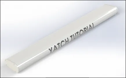
Fig.2 Radar
3. Blueprint Setup-
Blueprints are one of the most useful things for modelling a yacht in Solidworks. They are basically orthogonal drawings of the yacht in every direction (front, top, mid, bottom and back). They allow us to draw curves over a picture so that we can be precise and match the real shape of the yacht.
Features used to create blueprint setup-
- Rename the Planes:-
Front Plane – Front Plane of blueprint setup
Top Plane- Bottom Plane of blueprint setup
Right Plane-Mid Plane of blueprint setup
- Create Reference Geometry/ New Plane
Back Plane w.r.t front plane of blueprint setup
Top Plane w.r.t bottom plane blueprint setup
- Add sketch picture w.r.t each plane
Path- Tools>Sketch Tools> Sketch Picture (Import Picture from device)
Add the property values, transparency value
- Rename the Sketches w.r.t each planes
Eg. Blueprint _Isometric View
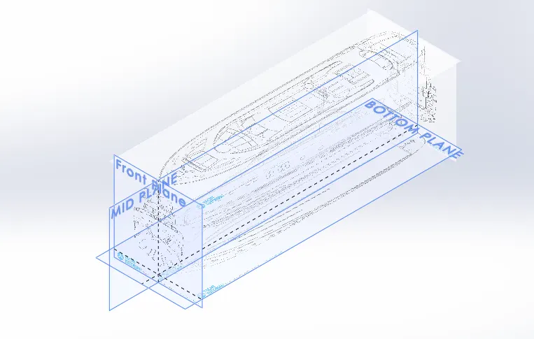
Fig.3 Blueprint Setup
4. Hull
The hull of a ship is the most notable structural entity of the ship. To define the hull, it can be said that it is the watertight enclosure of the ship, which protects the cargo, machinery, and accommodation spaces of the ship from the weather, flooding, and structural damage. The hull may open at the top , or it may be fully or partially covered with a deck. Atop the deck may be a deckhouse and othersuperstructure such as a funnel, derrick, or mast. The line where the hull meets the water surface is called the waterline.
Features used to create hull-
- Use Blueprint file
- Sketch
- Projected Curve
- Lofted Surface
- Trim Surface
- Knit Surface
- Filled Surface
- Shell
- Extrude Boss/Base
- Extruded Cut
- Fillet
- Chamfer
- Create Ref. Geometry/ New Plane
- Swept Boss/base
- Revolve Boss/Base
- Dome
- Helix/ Spiral
- Linear Pattern
- Delete Face
- Mirror
- Split
- Split Line
- Offset Surface
- Appearance –
Hull Body- White
Windows- Black
Lower Surfaces- Dark Blue
Floodlight- Dark Grey
Anchor- Light Grey
Railing, Port Hole, Anchor hole edges– Light Grey
- Edit Decals- Explained in decals topic.
- Save the part model- Hull
Note: - Save the splited garage body/block from the hull main body.
Path- Insert> Features> Split> Enable the “Consume Cut Bodies” > Change the name of resulting bodies to Garage_Door.sldprt.
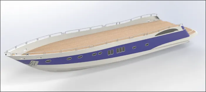
Fig.4 Hull
5. Garage Door
A garage door is a large doo that opens either manually or by an electric motor (a garage door opener). Garage doors are frequently large enough to accommodate automobiles and other vehicles. A garage door opener is a motorized device that opens and closes garage Doors controlled by switches on the garage wall. Most also include a handheld radio remote control, which can be used to open and close the door from a short distance.
Features used to create garage door-
- Open the exported body of the hull ( Garage_Door.sldprt)
- Sketch
- Extruded Cut
- Shell
- Fillet
- Mirror
- Reference Geometry/ New Plane
- Create the name of yacht: Yacht Tutorial
- Appearance:
Body- Dark Blue, RGB No- 0,0,128
Text Color- White
- Save the part model- Garage Door
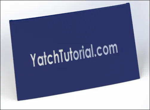
Fig.5 Garage Door
6. Front Seat
Marine passenger seats and chairs can be used on the fast ferry, high-speed passenger ship, cruise ship, catamaran, crew boat, cargo ship, the sightseeing boat, traffic boat, pilot launch, yacht and other passenger vessels. The material of the seats adopt fire-proof leather, PU/PVC leather or fabric according to customer's requirements. The anti-corrosion aluminum structure is durable. They all have beautiful appearance and special design which makes people more comfortable when seating.
The front seat is designed with reference of deck surface as a ground and the blueprint sketches to match the curve shapes.
Features used to create front seat-
- Use Blueprint file
- Import the deck surface of the Hull as an interface surface
Note- Only select surface bodies.
Path- Insert> Part>Surface Bodies
- Sketch on deck surface
Note- Use blueprint to match the curves.
- Swept Surface
- Extruded Surface
- Trim Surface
- Filled Surface
- Knit Surface
- Chamfer
- Revolved Boss/Base
- Extruded Cut
- Mirror
- Dome
- Appearance-
Front Seat- White
Mattress Body- Light Grey
- Save the part- Front Seat
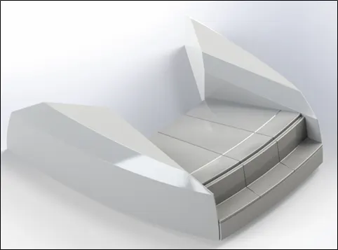
Fig. 6 Front Seat
7. Middle Seat
It is placed behind the garage door. The middle seat is also designed with reference of deck surface as a ground and the blueprint sketches to match the curve shapes. This is U shaped seat with table in the middle of seat.
Features used to create middle seat -
- Use Blueprint file
- Import the deck surface of the Hull as an interface surface
Note- Only select surface bodies.
Path- Insert> Part>Surface Bodies
- Sketch on deck surface
Note- Use blueprint to match the curves.
- Extruded Boss/Base
- Create Ref. Geometry/ New Plane
- Chamfer
- Fillet
- Extruded Cut
- Mirror
- Appearance-
Middle Seat- White
Mattress Body- Light Grey
Bottom Fillet of seat, Table- Grey, RGB No- 120,120,120.
Table Top- Light Brown, RGB No- 190,169,146.
- Save the part- Middle Seat
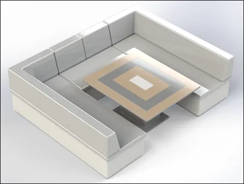
Fig. 7 Middle Seat
8. Rear Seat
It is placed in front of middle seat and rear side of deck surface. The rear seat is also designed with reference of deck surface as a ground and the blueprint sketches to match the curve shapes.it is provided with flag at the back side which is designed by surface tool.
Feature used to create rear seat-
- Use Blueprint file
- Import the deck surface of the Hull as an interface surface
Note- Only select surface bodies.
Path- Insert> Part>Surface Bodies
- Sketch on deck surface
Note- Use blueprint to match the curves.
- Create Ref. Geometry/ New Plane
- Swept Surface
- Offset Surface
- Ruled Surface
- Knit Surface
- Extended Surface
- Extruded Surface
- Trim Surface
- Lofted Surface
- Filled Surface
- Extruded Boss/Base
- Chamfer
- Revolved Boss/Base
- Extruded Cut
- Mirror
- Fillet
- Appearance-
Rear Seat- White
Locks, hinges and Railing- Grey
Flag- Red
Mattress Body- Light Grey
Lights- Light Yellow, RGB No- 255,255,227.
- Save the part- Rear Seat
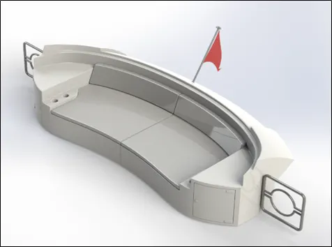
Fig. 8 Rear Seat
9. Superstructure
A superstructure is an extended construction that rises above an already existing structure. The word comes from a combination of two Latin words, the Latin prefix ‘super’ means in addition or above or in excess of, whereas the stem word ‘structure’ means to build or to heap up. In ships this is the name given to the part of the ship that emerges from the deck.
Features used to create superstructure-
- Use Blueprint file
- Import the deck surface of the Hull as an interface surface
Note- Only select surface bodies.
Path- Insert> Part>Surface Bodies
- Sketch on deck surface
Note- Use blueprint to match the curves.
- Create Ref. Geometry/ New Plane
- Swept Surface
- Projected Curve
- Ruled Surface
- Knit Surface
- Extended Surface
- Extruded Surface
- Trim Surface
- Lofted Surface
- Filled Surface
- Extruded Boss/Base
- Offset Surface
Note- Rename the surface as a Radar_Mast_Reference
- Delete Face
- Extruded Boss/Base
- Extruded Cut
- Chamfer
- Revolved Boss/Base
- Extruded Cut
- Mirror
- Fillet
- Appearance-
Superstructure- White
Windows- Black
Jacuzzi Waterline- Light Blue, RGB No- 192,255,255
Mattress Body- Light Grey
Stairs- Light Brown, RGB No-190,169,146
Save the part- Superstructure
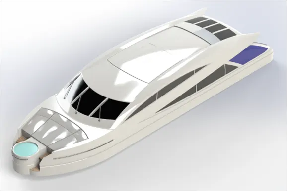
Fig.9 Superstructure
10. Radar Mast
A radar most mount is consist of components such as radar scanner, antenna, navigation light, Radom, fog horn, etc. it is designed using top surface of superstructure and blueprint setup file.
It is a tall pole used for support of the sails on a boat and hold radar on a ship.
Features used to create radar mast-
- Use Blueprint file
- Import the Radar-Mast_Reference surface of the superstructure as an interface surface.
Note- Only select surface bodies.
Path- Insert> Part>Surface Bodies
- Sketch on deck surface
Note- Use blueprint to match the curves.
- Create Ref. Geometry/ New Plane
- Extrude Boss/base
- Revolve Boss/bass
- Projected Curve
- Swept Boss/Base
- Extrude cut
- Shell
- Mirror
- Fillet
- Chamfer
- Dome
- Appearance-
Radar Mast Body- White
Horn- Light Grey
Antenna- Grey
- Save the part- Radar Mast
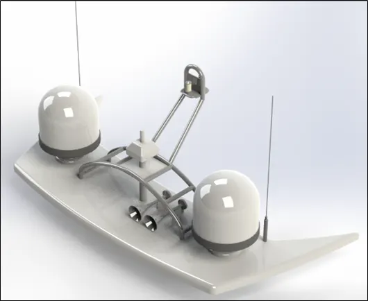
Fig.10 Radar Mast
Assembly of Sunseeker Predator 108 Yacht
- All part modelling windows should be opened.
- Initially, hull part is inserted in to the main assembly environment by using insert part option and press ok to fix the hull.
- Similarly other parts also inserted into the main assembly environment and give them possible mates to fully define. Following is the part insertion sequence:-
- Hull
- Superstructure
- Radar Mast
- Front Seat
- Middle Seat
- Rear Seat
- Garage Door
- Propeller
- Radar Mast
Note: Insert propeller three times and give mates to make fully defined assembly.
Features used to create assembly-
- Insert Components
- Mates
- Save the assembly- Yacht
Insert components
We can insert component in the assembly which is need to be mated with fix component.
Mates
Mates creates geometric relations with the components which are inserted into the assembly. While making assembly we used various type of mates like –
- Standard Mates- concentric, parallel, coincident, tangent, distance, angle, etc.
- Advanced Mates- Limit, Width, etc.
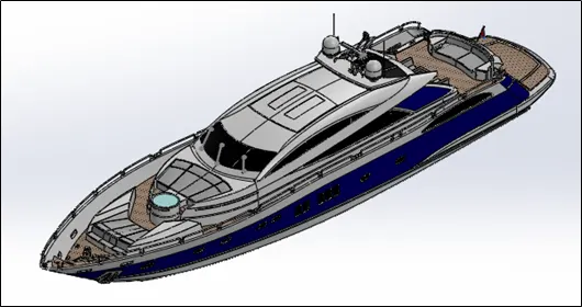
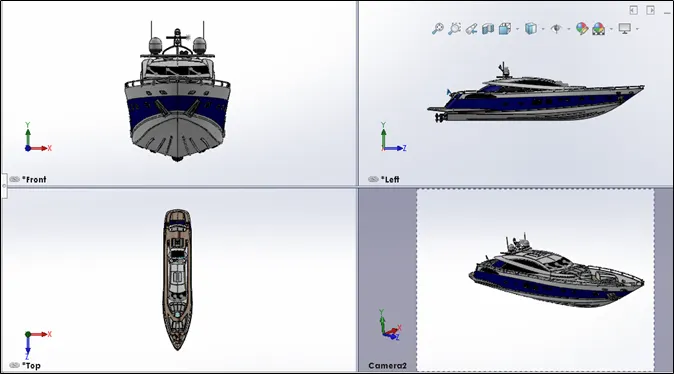
Fig.11 Isometric, Front, Top, Left Side and Camera View of Yacht Assembly
Decals used for Sunseeker Predator Yacht
- We can apply decals to a part faces, rather than to an assembly because we cannot select specific faces.
- Path- Click PhotoView 360 > Edit Decal,
Decals used in-
- Deck surface, Stairs, Garage Surface of hull.
- Superstructure- Stairs
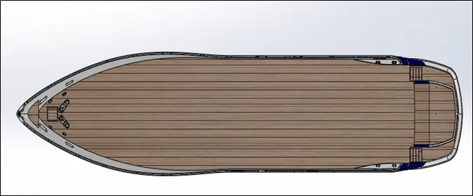
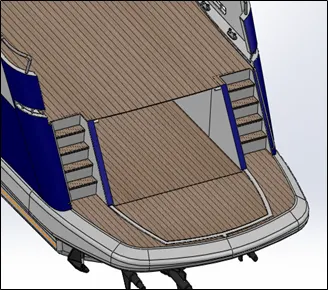
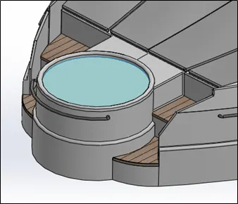
Fig. 12 Decals on hull and superstructure resp.
Rendering of Sunseeker Predator Yacht
Rendering is process of creating realistic images of the model with environment. In rendering various aspects such as camera, light, environment, background scene, appearance, etc. are taken in consideration before final rendering. To check the all thing preview rendering option is used.
There are two ways of rendering in SOLIDWORKS.
- Photoview 360
- Solidworks Visualize
In photorealistic model, some of the mates and conditions are changed to render realistic model. So we have to change as per different view before rendering.
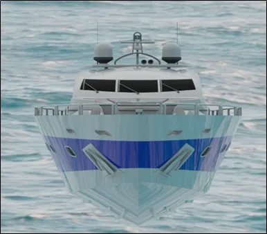
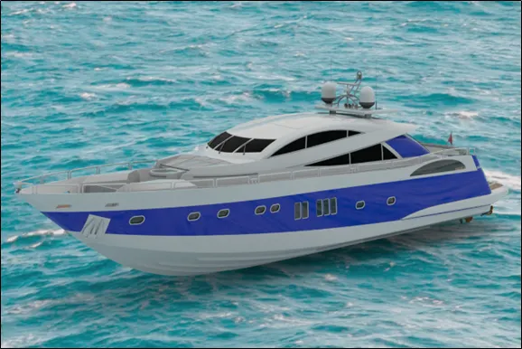
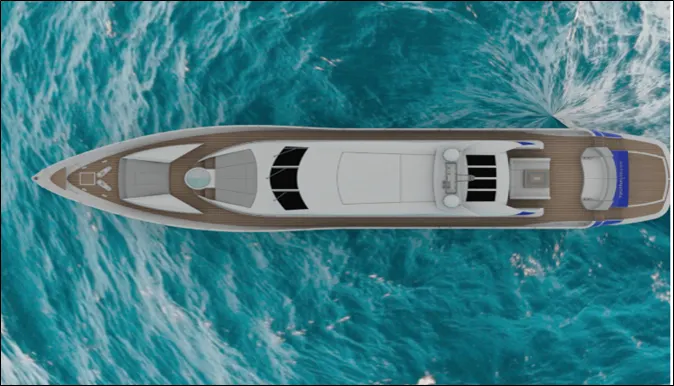
Fig. 13 Rendered images of Sunseeker Predator Yacht Assembly
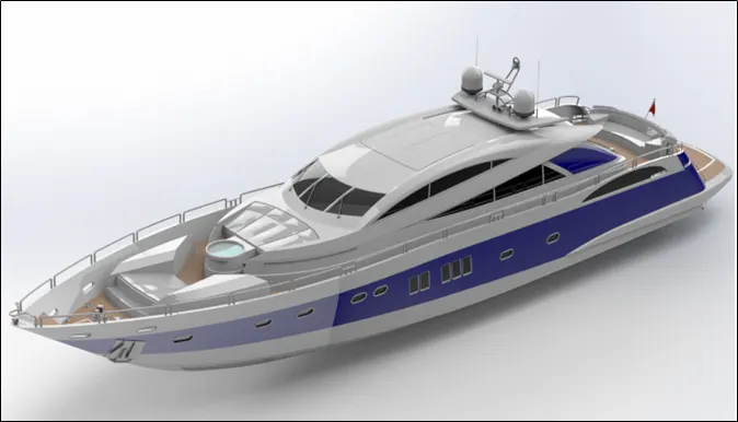
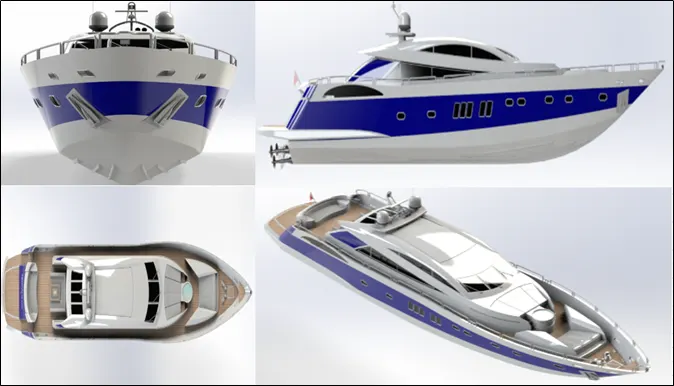
Fig. 17 Rendered images in Isometric, Front, Left, Top, and Camera View
Conclusion:-
- The parts are sketched and modelled in the SOLDWORKS.
- The modelled parts are assembled with possible mates in to the main assembly of yacht.
- The decals are applied to faces of parts.
- The realistic images was rendered with use of both ways “Photoview 360 and Solidworks Visualize.
- This project has helped to enhance the skills in surface modelling and product design.
- It has given me insight into marine vehicle design and opportunity to build one.
Please Find attached feature tree and view images for radar mast and yacht assembly.
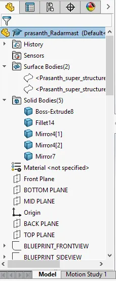
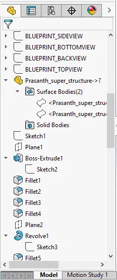
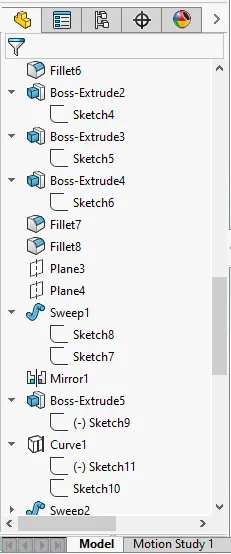
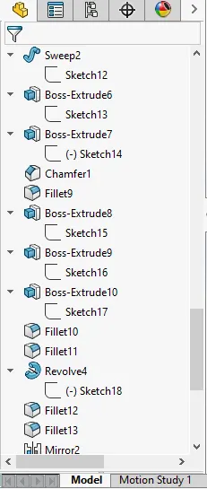
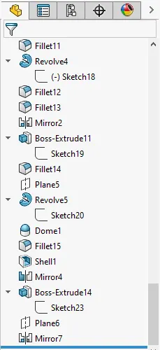
Fig.18 Radar Mast Feature Tree
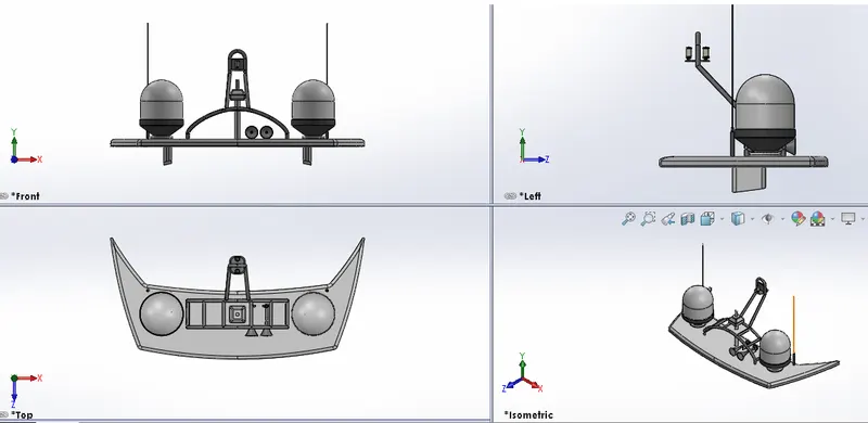
Fig.19 Radar Mast View Images
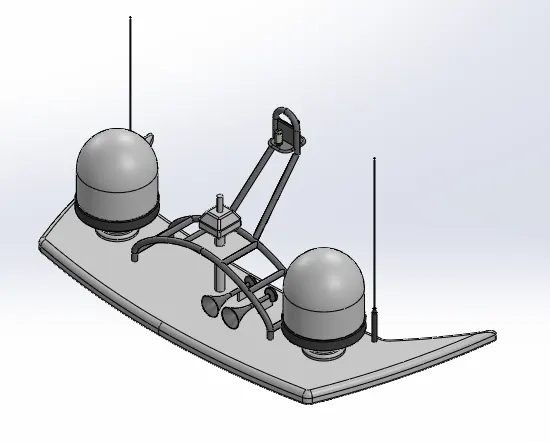
Fig.20 Radar Mast Isometric View Images
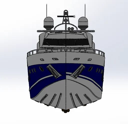
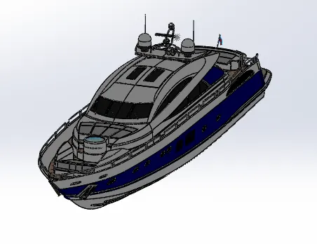
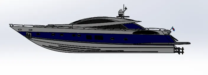
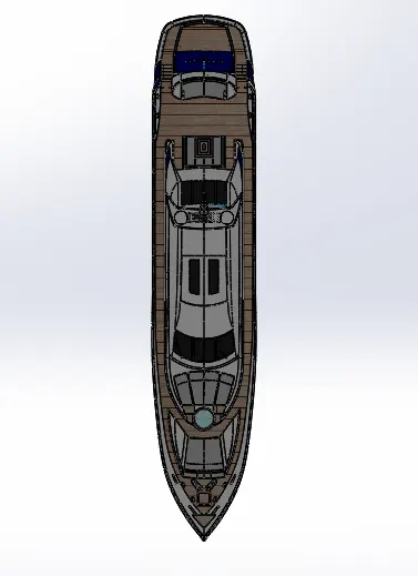
Fig.21 Yacht Assembly View Images
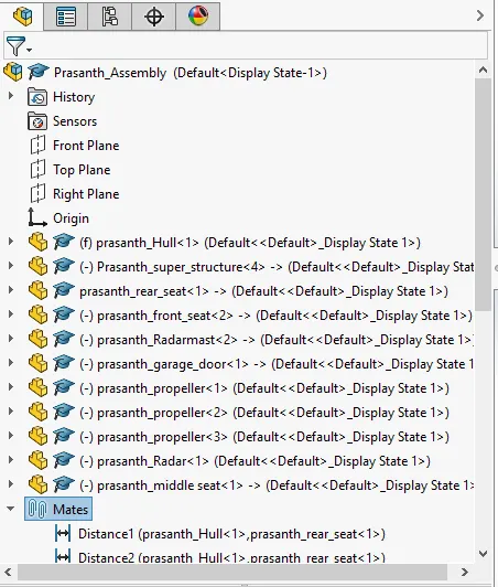
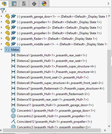
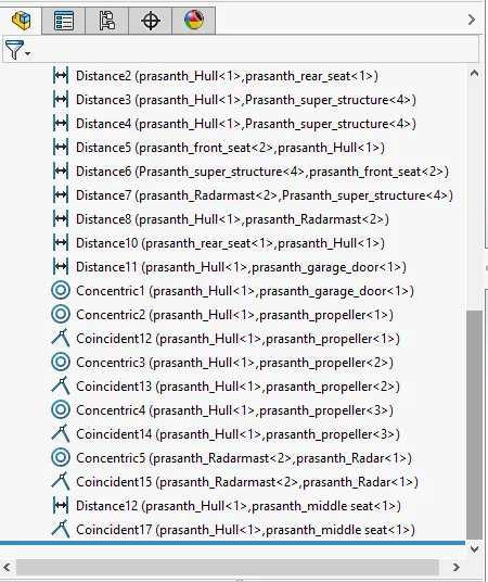
Fig.22 Yacht Assembly Feature Tree