Advanced Sheet Metal Design Using NX Cad Challenge_1_Casing Design
SHEET METAL DESIGN OF CASING USING NX-CAD
OBJECTIVES
- To design casing in NX sheet metal.
- To draft the casing.
INTRODUCTION
The sheet metal is a simple metal formed into thin and flat pieces .It is one of the fundamental forms used in metalworking and can be cut and bent into a variety of different shapes.
The NX CAD is formerly known as unigraphics is an advanced high end CAD/CAM/CAE software which has been owned since 2007 by Siemens PLM software.
In this design the casing is designed with the help of basic sheet metal features. It is designed using Siemens NX10.
DESIGN APPROACH:
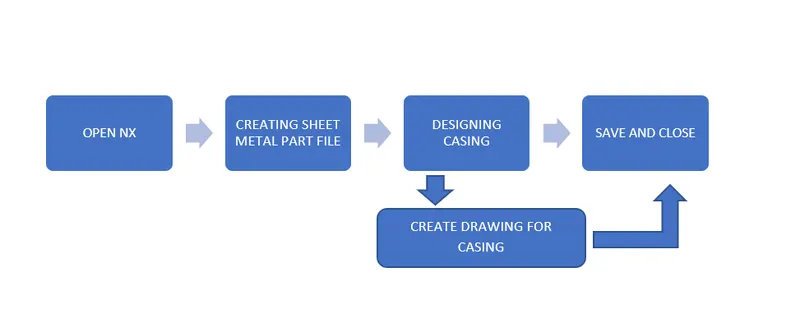
DESIGN METHODOLOGY:
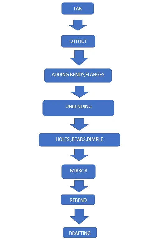
TOOLS AND FEATURES USED ON SHEETMETAL TO DESIGN CASING
- Sketch
- Tab
- Cutout
- Bend
- Flange
- Break corner
- Unbend
- Hole
- Studio spline
- Move curve
- Dimple
- Bead
- Re bend
- Drafting
- Base view
TOOL AND FEATURE DESCRIPTION
- SKETCH
It is a 2d representation of a 3d part. It includes entities like line, rectangle, spline, circle, etc. It is a predetermined drawing with dimensions and relations.
- TAB
It is the base part for any sheet metal design. Flanges can be made only from the tab edges.
- CUTOUT
This command is to remove the desired shape of material. Removal sketch can be drawn on the sheet metal face, wherever required.
- BEND
It is to bend the tab/flange by creating the line sketch. The bend can be like U, v or channel shape.
- FLANGE
It is created with one or more edges at specified location. The minimum flange length must be atleast four times the thickness of the sheet metal. Bend radius is equal to the sheet metal thickness.
- BREAK CORNER
This command gives a smooth finish over the corners of the sheet metal part.
- UNBEND
It makes the part unbend, that is all the features done are made flat. This is useful while sketching on the corners and bend areas.
- HOLE
This feature is to put a hole on the part. There were screw type hole with specified scre size and fit.
- STUDIO SPLINE
It results in a set of splines after selecting the points for its path. It is used for making splines along the sketch.
- MOVE CURVE
It moves or rotates your curve.
- DIMPLE
It rises a drawn sketch from the base plate. This command doesn’t save material instead it maintains the rigidity.
- BEAD
It lifts material along contour sketch.
- REBEND
This command puts back all the bends already created also along with new features included while in unbent state.
- FLAT PATTERN
It is done before drafting. It gives a flattened version of the sheet metal part.
- DRAFTING
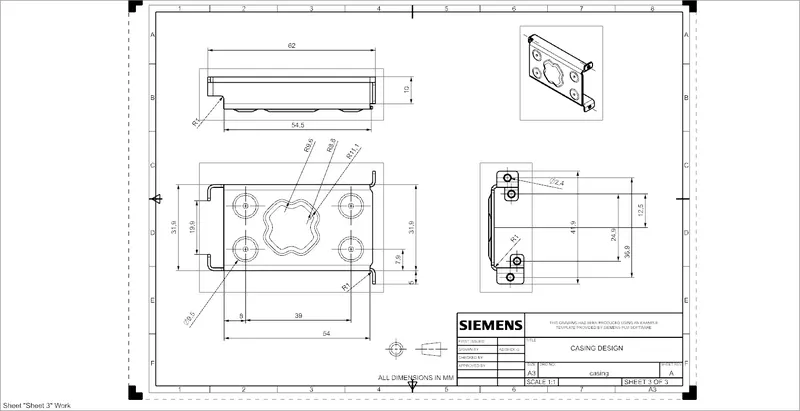
This command is to have 2D drawing of the sheet metal part created.
- BASE VIEW
It specifies the location, orientation, view and scale of the part for drafting.
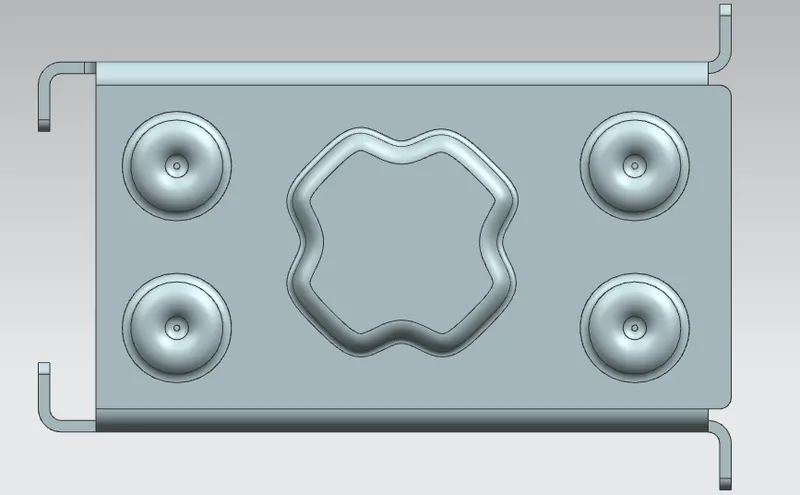
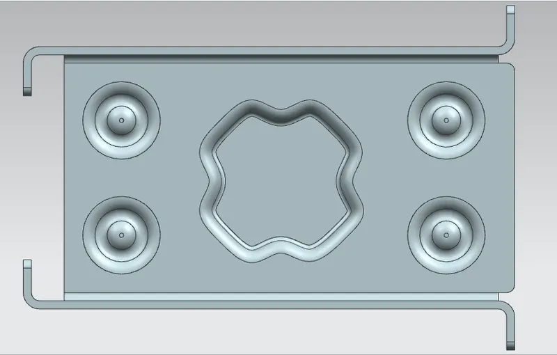
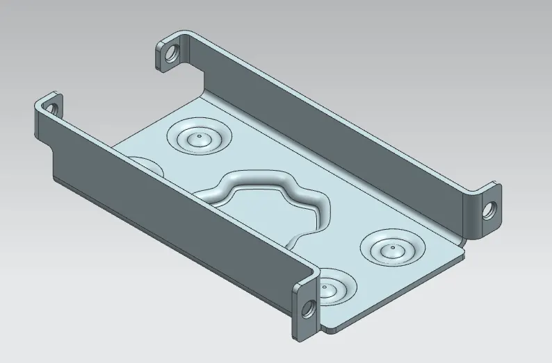
CASING IMAGES
BOTTOM VIEW
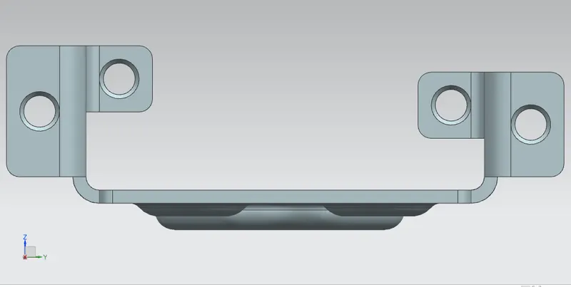
SIDE VIEW
TOP VIEW
ISOMETRIC VIEW
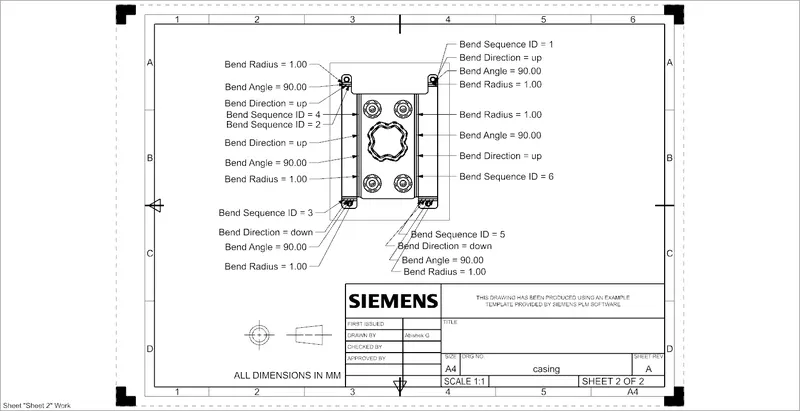
DRAFTING
Creating a new draft on A4 size sheet of flat pattern#1.
CONCLUSION
The casing sheet metal part is created using NX10 software.