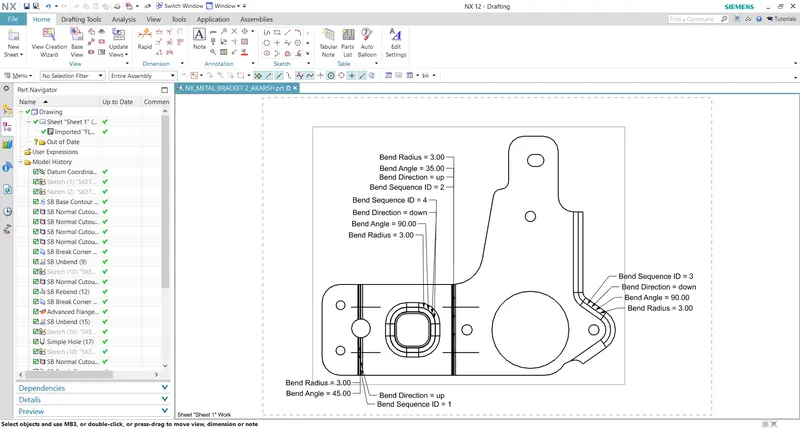
Advanced Sheet Metal Design Using NX Cad Challenge_7_ Metal bracket-II
DESIGN OF METAL BRACKET
OBJECTIVE:
To understand the step by step procedure to design the metal bracket using NX CAD
INTRODUCTION:
Sheet metal fabrication includes important design considerations to help improve part manufacturability, enhance cosmetic appearance and reduce overall production time.
Sheet metal fabrication is the process of forming parts from metal sheet by punching, cutting, stamping and bending.
3D CAD files are converted into machine code, which controls a machine to precisely cut and form the sheets into the final part.
Sheet metal parts are known for their durability, which makes them great for end use application. Parts used for low volume prototypes and high volume production runs are most cost effective due to large initial setup and material costs.
Because parts are formed from a single sheet of metal, designs must maintain a uniform thickness. We have to be sure to follow the design requirements and tolerances to ensure parts fall closer to design intent and cutting sheets of metal.
DESIGN METHODOLOGY:
TOOLS AND FEATURES USED TO DESIGN METAL BRACKET:
SKETCH: Sketch is the two dimensional representation of the model, in NX CAD there are different sketch options available to create sketch, the following are the sketch entities available in solid works line, arc, circle, rectangle.
ADVANCED FLANGE: Adds a flange along the edge using the reference face or bend angle. The edge and reference face can be curved.
BREAK CORNER: Feature rounds/fillet sharp corner.
NORMAL CUTOUT: Cuts the model perpendicular to the sketch.
UNBEND: Flattens a bend.
REBEND: Restores a bend.
GUSSET: Gusset is used to strengthen the bent edges.
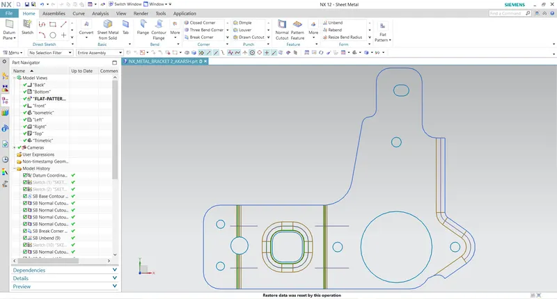
FLAT PATTERN: Creates flat pattern feature from formed sheet metal part.
FLOW CHART:
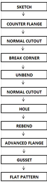
STEP BY STEP PROCEDURE TO DESIGN BRACKET
STEP 1: Draw 1st sketch on YZ plane & 2nd sketch on XZ plane.
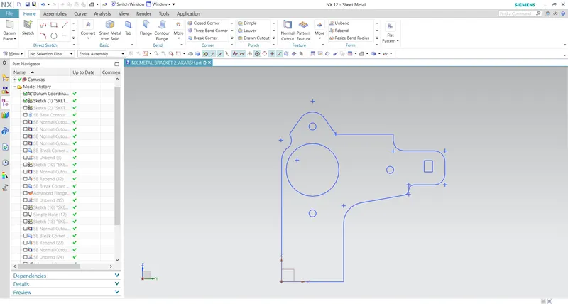
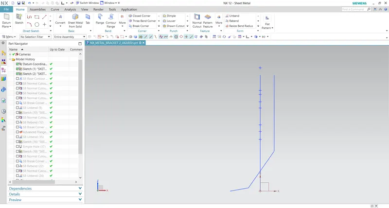
STEP 2: With reference to 2nd sketch create a counter flange and with reference to 1st sketch trim(eleminate) the unwanted portion from using normal cut option
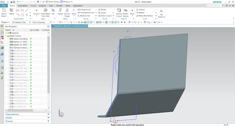
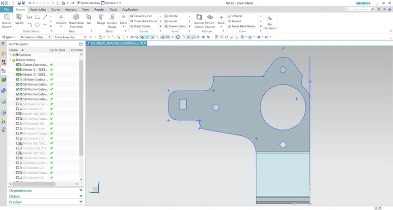
STEP 3: Use break corner option to make round corners and unbend the bracket.
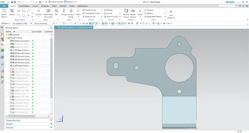
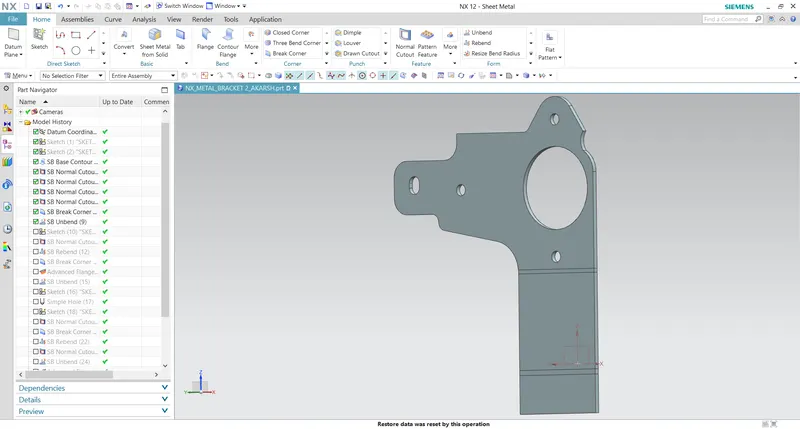
STEP 4: Sketch a circle and cut the portion using normal cut option and rebend the bracket.
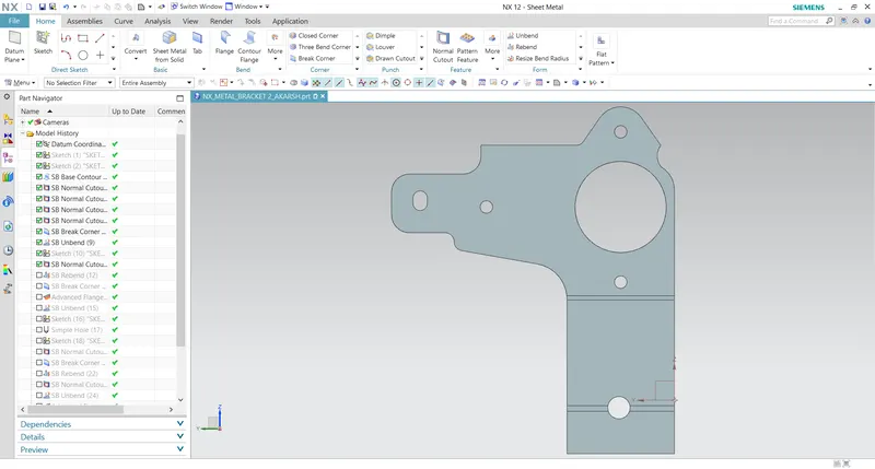
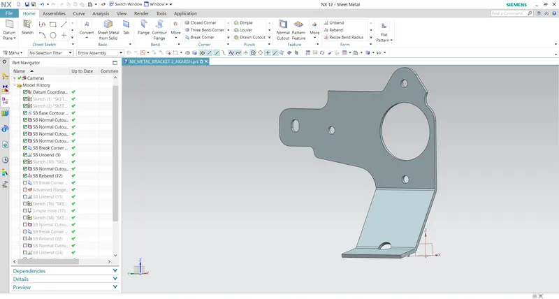
STEP 5: Click on the advanced flange option and select the top edge as shown the picture and unbend the bracket.
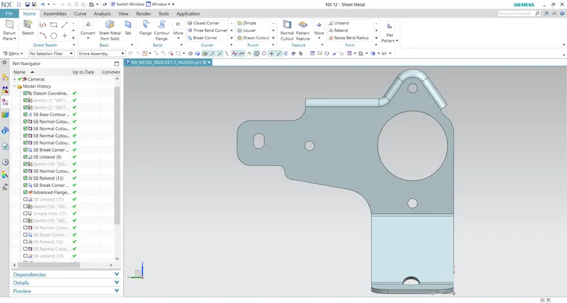
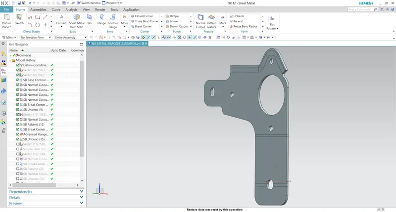
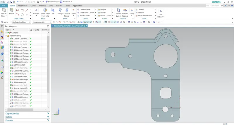
STEP 6: Sketch a circle and trim the surface using normal cut option as shown in the picture and the select the hole command to create holes and add advanced flange to the cut portion as shown in the picture.
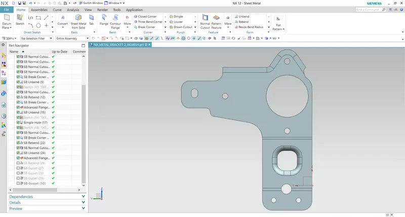
STEP 7: Rebend the bracket and create flat pattern.
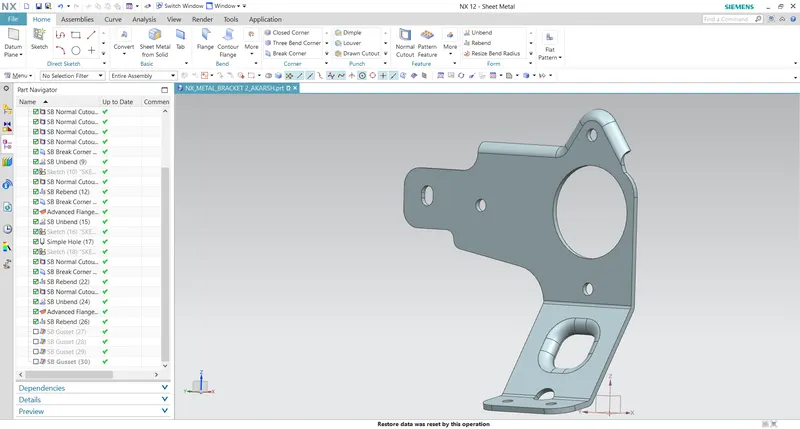
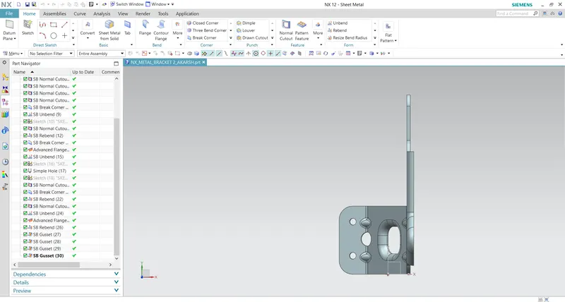
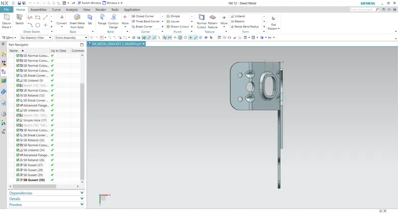
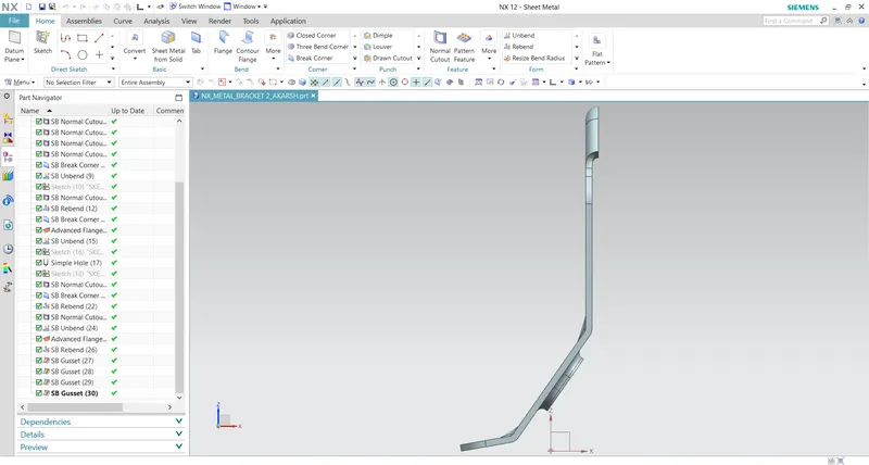
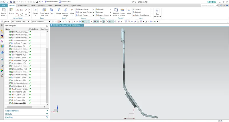
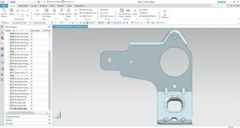
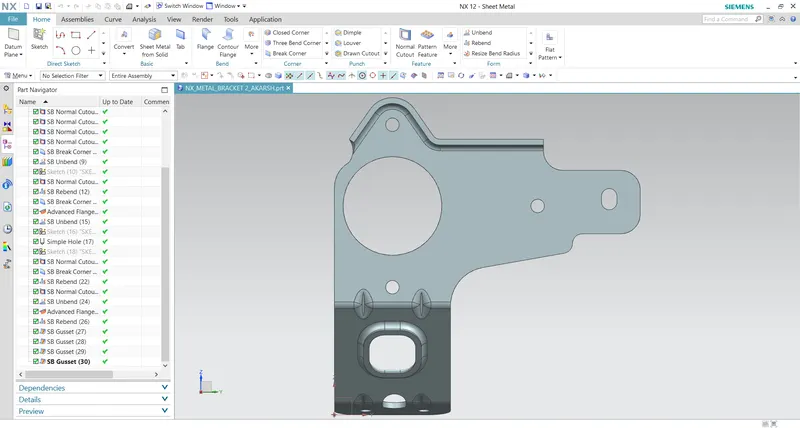
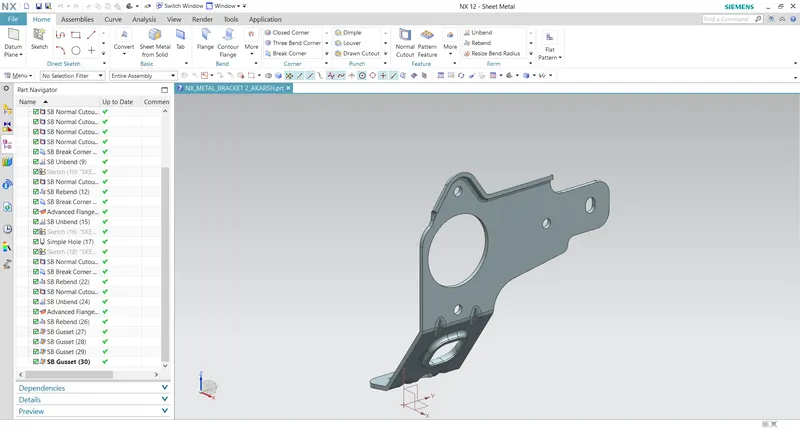
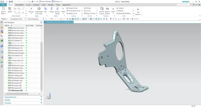
FINAL DESIGN OF METAL BRACKET: