Advanced Sheet Metal Design Using NX Cad Challenge_7_ Metal bracket-II
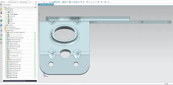
front view
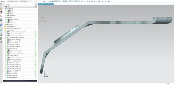
side view
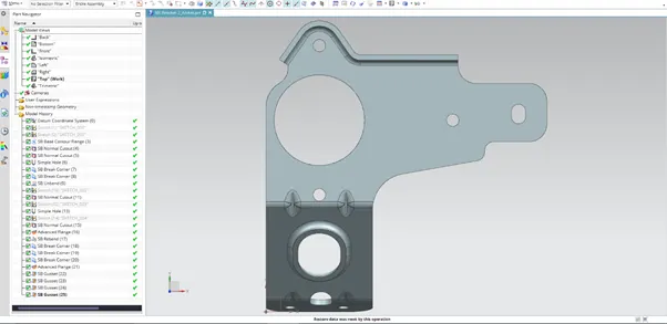
Top view
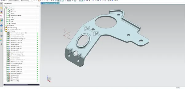
isometric view
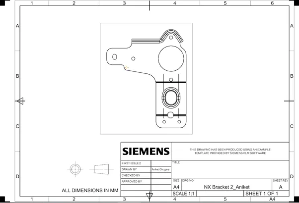
drawing sheet
Report
Metal Bracket Design 2
Objective:
To create a 3D model of second sheet metal Bracket using siemens NX.
Introduction:
In this project a detailed model of a bracket is created using Siemens NX in-order to understand and familiarize with different tools and methods of sheet metal design.
Design Methodology:
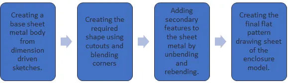
Description:
Siemens NX has a large set of sheet-metal tools. These tools have a wide range of applications.
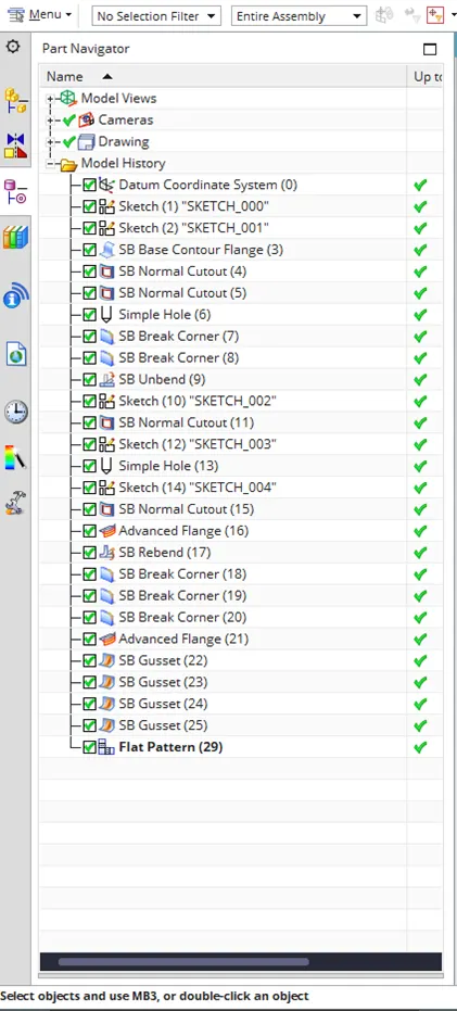
For the bracket design, the following tools and features are used:
- Contour Flange: The contour flange creates a flange along a curve or sketch. This flange can be a secondary feature to a base sheet or it can be used as a base body itself. The direction and distance of flange can be adjusted manually.
- Normal cut-out: The normal cut-out tool creates a cut of the selected curve or sketch on a target body. The cut can be a through cut or a distance cut as per requirement.
- Break corner: The break corner tool is used to remove sharp edges from the model. The edges can be blended (rounded) or chamfered. The dimensions of blend or chamfer can be modified
- Unbend: This tool unbends/flattens a selected body along a stationary face. The features to be flattened should be connected to the stationary face.
- Re-bend: The re-bend tool bends the selected parts of the body that were flattened using unbend tool.
- Advanced Flange: This tool creates a flange at the selected edges. These edges can be curved or straight. The bend radius and distance can be locally adjusted as per requirement.
- Gusset: The gusset tool creates a stiffening gusset at the selected face. The gusset can be of square or round type. The position of gusset is defined by giving an offset distance from a reference face. The depth, radius and angle can be adjusted locally.
- Hole: It creates a hole in the selected body. There are various options available for hole specifications such as drill hole, screw clearance hole, threaded hole etc. The holes are created on user defined sketch points. The dimensions and direction can be manually adjusted.
- Flat pattern: The flat pattern tool creates a flat pattern view of the body which can be imported in a drawing sheet.
The below image shows all the tools used for creating the box assembly model.
Bracket Design views:
Front view
Top view
Side view
Isometric view
Bracket Drawing Sheet:
Conclusion:
Thus, by following the steps mentioned in methodology and using the above-mentioned tools and features, the second bracket design is complete.