Advanced Sheet Metal Design Using NX Cad Challenge_6_Bracket
Design of brecket using NX CAD
Objective:
- Make a bracket according to the given dimesions of the drawing
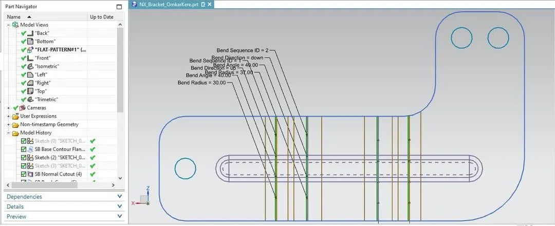
- Make a flatpattern
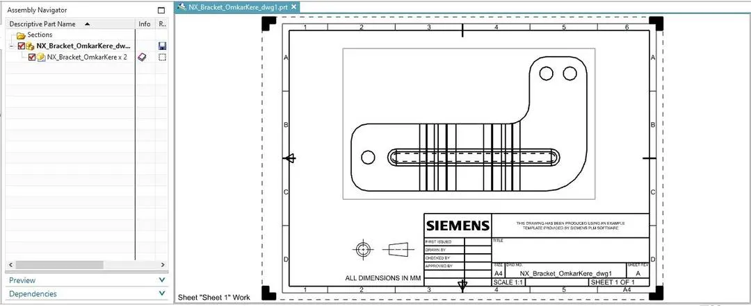
- Make a Drawing on the A4 sheet
Introduction:
A bracket is designed using NX CAD software
Design methodology:
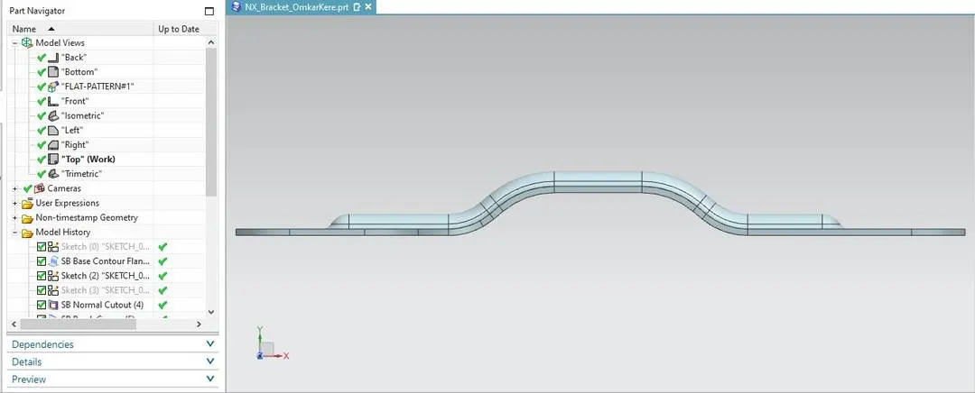
Make a new sheetmetal part --> Select the datum plane --> Make a sketch according to the dimension given in the figure --> Make a 340mm line in X-direction --> Make a 70mm line in x-direction; 20mm above in y-direction --> Join the two ends of the smaller line with bigger line using line option --> Join the line 110mm away from the origin at 40 deg --> join the other line at 40 deg --> Use quick trim to remove the unwanted line --> Use Fillet commant and make 30mm and 40mm fillet on both the lines --> Use contour flange to make the part --> Used Break corner command to make rounded corners --> Make a sketch to cut a rectangle --> Use normal cutout to remove the part --> Unbend the part using unbend option --> make a line Length: 255mm; y-axis: 150mm; x-axis: 40mm --> Used Bead command to make a bead --> Cross-section: circular; Depth: 7mm; Radius: 7mm; End condition: Formed --> Make three points --> First, x-axis: 315mm; y-axis: 150mm --> Second, 25 mm on x-axis; 25mm on y-axis --> Third, Horizontal to second hole and 35mm away from second in x- direction --> Use hole command to make holes in the sheetmetal using the points --> Rebend the sheetmetal part using Rebend command --> Used Flatpattern command to make the flatpattern.
Description:
- Sketch: This is used for creating Sketch.
- Line: For sketching lines.
- Fillet: For making rounded corners in sketch.
- Countour flange: For making sheetmetal part from the sketch.
- Break Corner: For making rounded corners in sheetmetal.
- Normal cut: Used for cutting parts based on the sketch.
- Bead: Used for making hump/bead on the part.
- Hole: For creating holes.
- Unbend: For unbending the part.
- Rebend: For rebending the part.
- Flatpattern: For making flatpart.
Images:
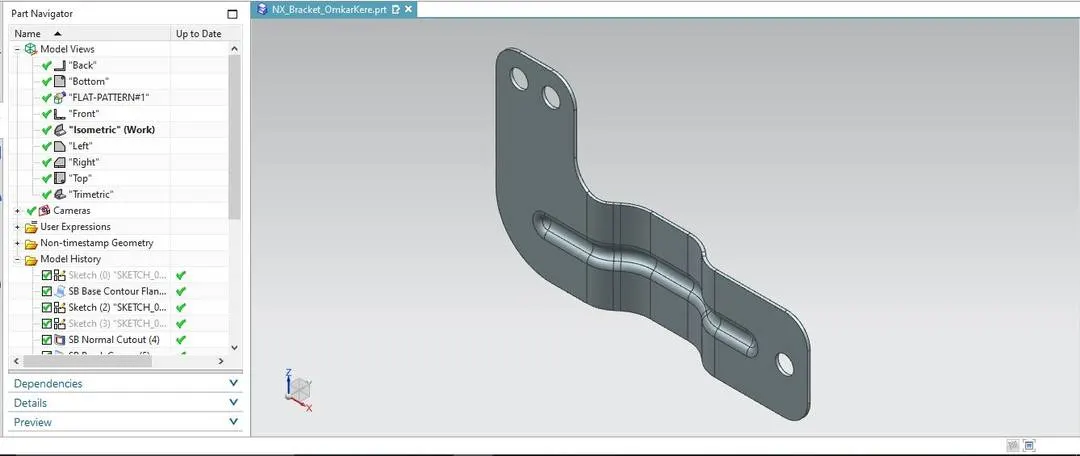
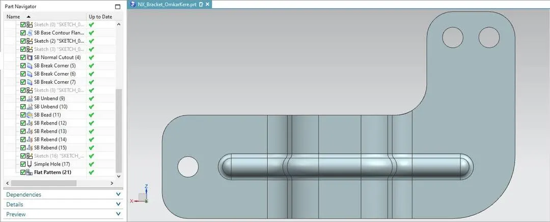
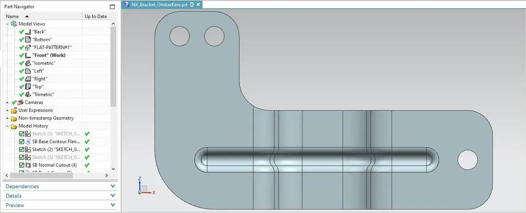
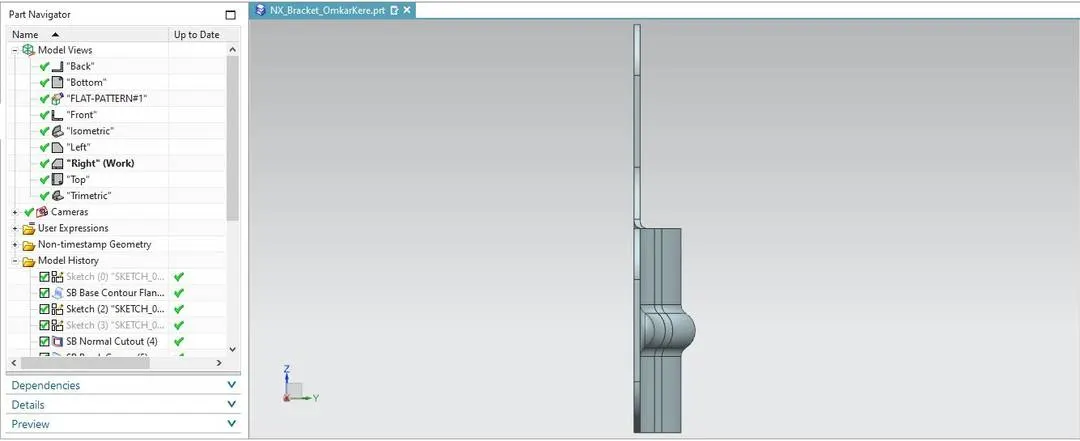
Flatpattern Images:
Drawing Image:
Conclusion:
The sheetmetal part was designed according to the given dimensions of the image. The flatpattern was made and was drawn on an A4 sheet.