Advanced Sheet Metal Design Using NX Cad Challenge_6_Bracket
Title -Designing a sheet metal bracket
Objectives-
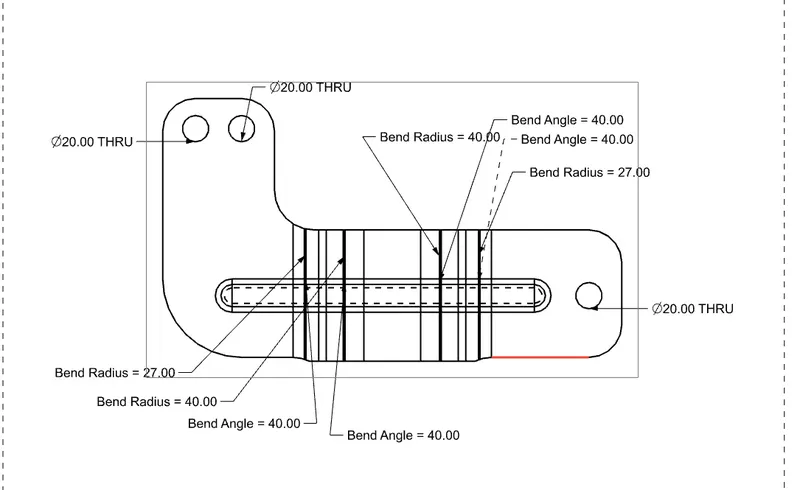
1) design a sheet metal bracket useing given 2D sketch
2) Get familiar with nx sheet metal tools .
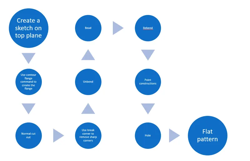
Design methodology flow chart
Tools used for designing
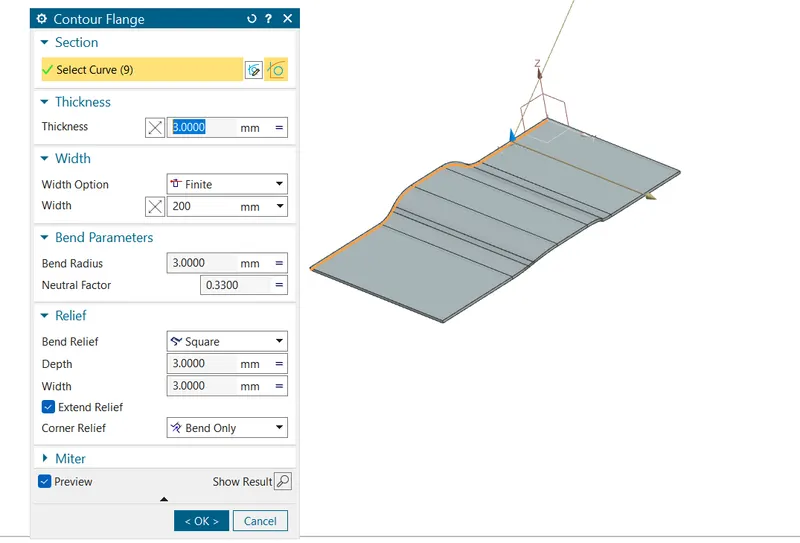
1. Contour flange - The sketh is extruded with thickness by useing contour flange command , here we have to specify the sketch , thickness, thick direction , width of flange , bend radius
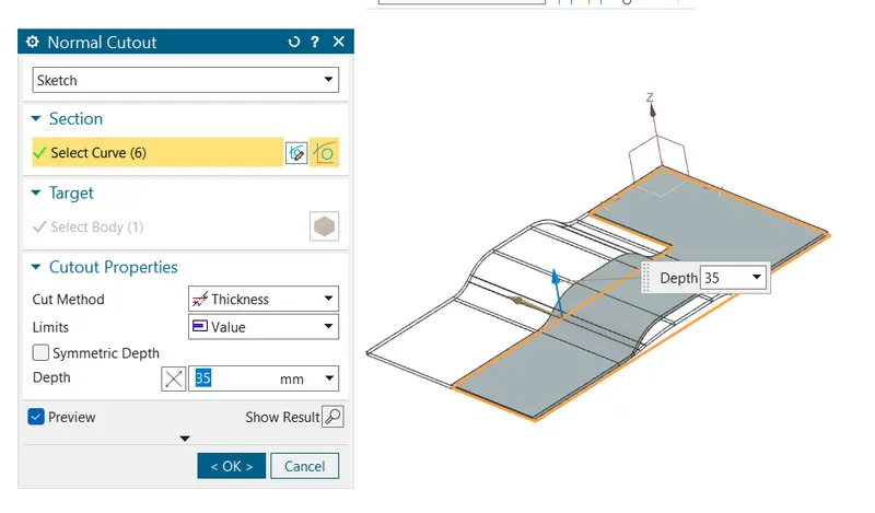
2.Normal cut out -This command is used to cut the base with respect to sketch . for useing this command we have to give sketch and depth as an input
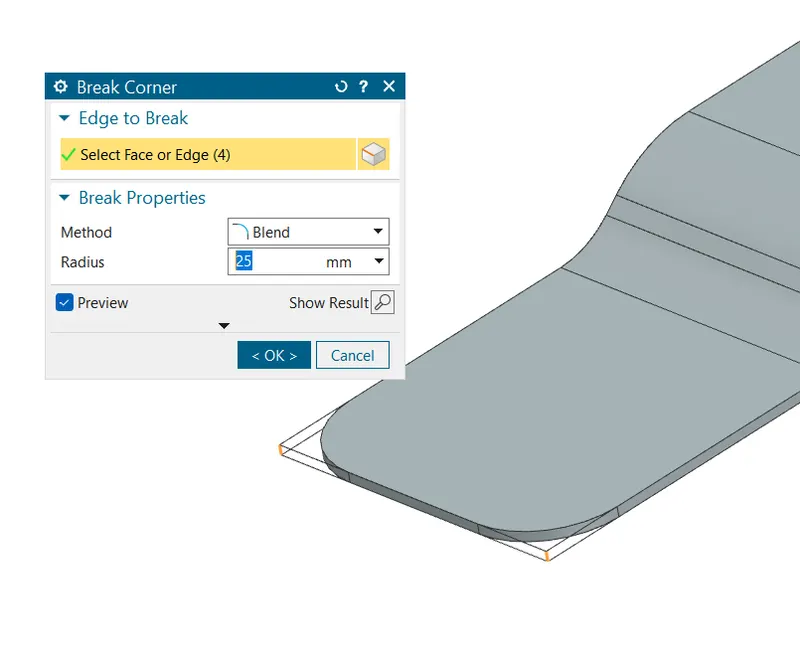
3.Break corner - this command removes the sharp corners of sheet metlal. we have to provide fillet radius value in this cammand
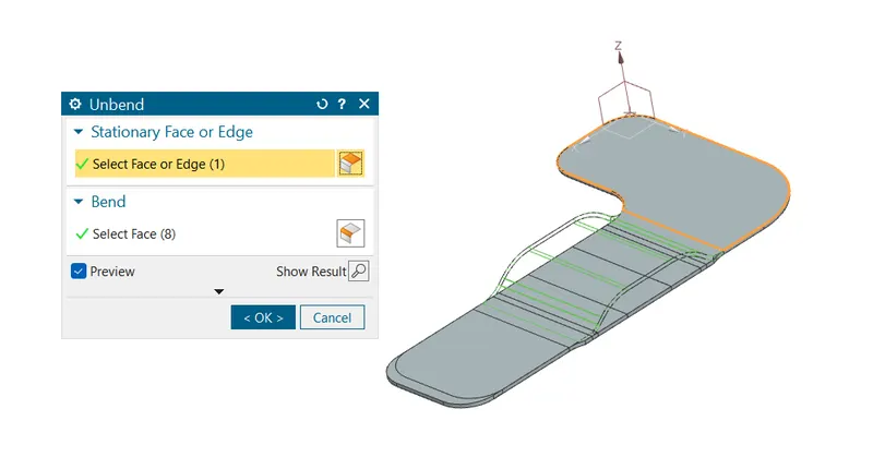
4.Unbend - In order to construct a bead we have to make the sheet metal component as a flat sheet over which we have to sketch the sketch .in this we have to select the stationary face and then all component body . by this command the component body is transformed into flat sheet
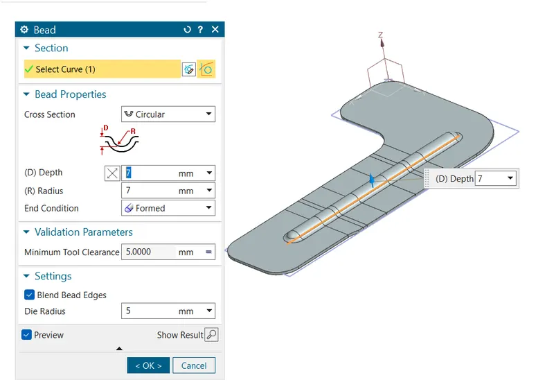
5.Bead- inputs for bead are curve and depth ,Radius , Die radius
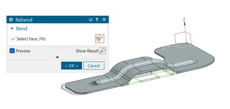
6.Rebend - This commands makes the unbend command to bend i.e flat body is trasformed to component body
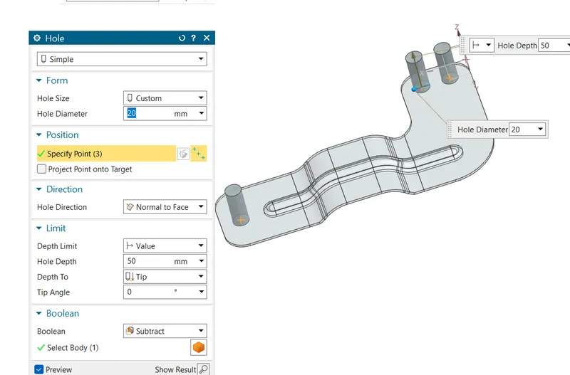
7.Hole -This command creates the hole in the body . we have to specify the points for location of hole
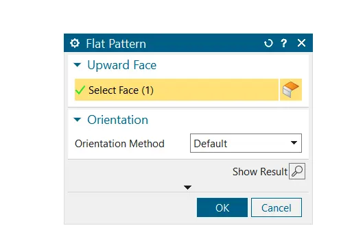
8.Flat pattern - In order to make all operation visible we are useing the flat pattern command .
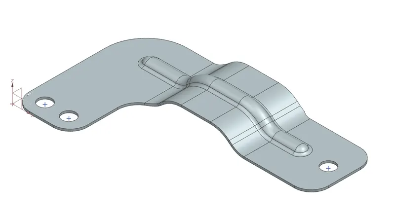
Views of the component
1.Isometric view
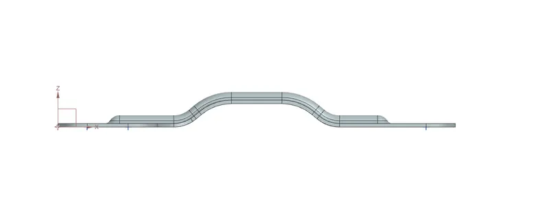
2.Front view
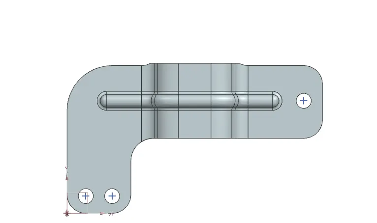
3.Top view
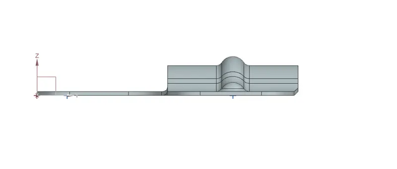
4.Side view
Drafting sheet