Advanced Sheet Metal Design Using NX Cad Challenge_6_Bracket
DESIGN OF SHEET METAL BRACKET USING SIEMENS NX CAD
Objective
To design a sheet metal bracket and adding features with reference to the input data and by following the industrial design methodologies for manufacturing a sheet metal component.
Introduction
Sheet metal is any metal that has a thickness in between 0.4 to 6 mm and it can be obtained by any metal rolling process method (cold rolled and hot rolled). Sheet metal widely used in industries like automobile, aerospace, electronic appliance, medical, construction, furniture, etc. To utilize sheet metal to its full extent we must understand standard measurements, materials, differences in manufacturing, possible forming methods and the material properties.
Sheet metal fabrication is the process of forming metal sheets to the desired shape using different manufacturing methods.
SHEET METAL BRACKET
Brackets are connecting devices used to join two objects. In addition to creating a connection between two parts, a bracket may provide support. Some brackets, such as gusset brackets, are designed with a diagonal section that reduces the strain on the bracket and allows it to support heavier loads.
Brackets typically consist of two or more planes connected along one edge, and often to simplest way to fabricate this kind of object is to bend a flat sheet metal(blank) in two or more places: the simplest example would be adding a 90° bend to a flat rectangle with a straight profile, turning it into a bracket with an L-shaped profile. Brackets often have holes in them, either threaded or unthreaded, so that screws or other fasteners can be fed through them, but this is not a defining feature of the bracket.
Most brackets are functional, with their purpose being to connect and support objects. However, brackets can also be decorative: since brackets are often visible. Sheet metal bracket used to support objects like shelving, countertops, flooring, sections of furniture, electrical appliances and machineries.
Design methodologies
- Brackets can be made from a variety of metals, depending on certain factors, including: the load it must support, cosmetic requirements, surface finishing requirements, minimum and maximum thickness, required bending angles, and budget for manufacturing.
- To designing a sheet metal bracket, it is always important to understand the aesthetic and functional requirements of the product in every design process.
- The starting point is determining what loading your metal part will be required to hold.
- The next step is to choose best fit metal by considering, product requirements & application of sheet metal bracket. The best metals are those that offer premium quality while providing wear and corrosion resistance.
- Choosing the right shape and dimension of the bracket is another one of the crucial design consideration and will be determined by the shape of the item it is holding up but will also be affected by the load capabilities and the ease in manufacturing.
- Adding specific features to the bracket can improve strength dramatically and also can be improved by adding more profile to the metal part.
- As the main purpose of the sheet metal bracket is to joining two objects we should consider the provision cutout for screws and other fasteners while designing the sheet metal bracket.
Steps followed
- Create the fully constraint sketch for the base body by following all the dimensions from the input data.
- Convert the fully constraint sketch into sheet metal part by using counter flange command.
- Remove the unwanted areas from the base sheet by using normal cut command with the help of the predefined fully constraint sketch.
- Give proper curvature to the required areas of the sheet metal body by using the break corner command.
- Unbend the developed sheet metal bracket body by using unbend command.
- Bead is applied to the required position with the help of sketch.
- Rebend the sheet metal and convert to its original shape.
- By using points in the fully constraint sketch and with the help of hole command holes are provided to the required positions.
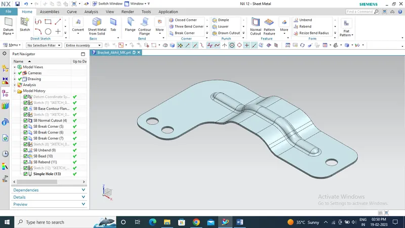
ISOMETRIC VIEW OF SHEET METAL BRACKET
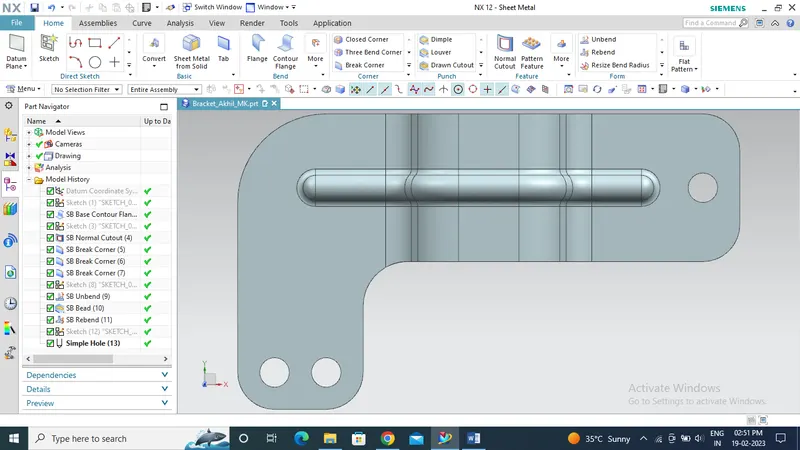
TOP SIDE VIEW OF SHEET METAL BRACKET
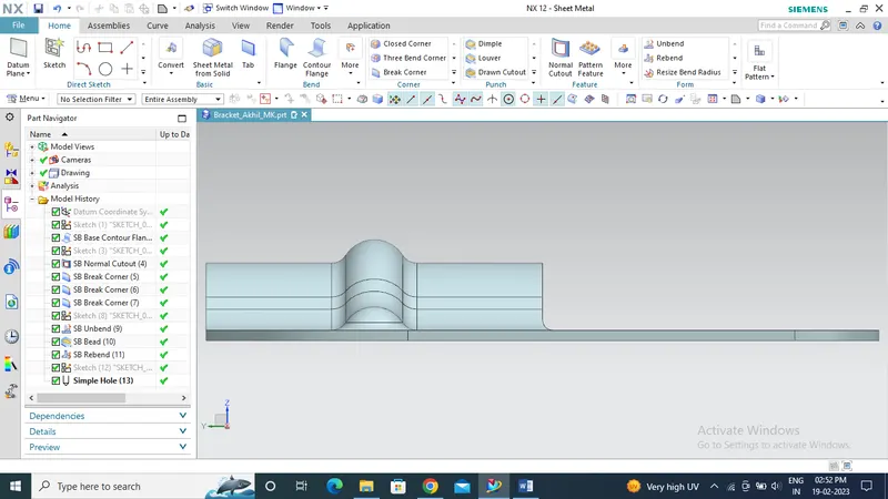
LEFT SIDE VIEW OF SHEET METAL BRACKET
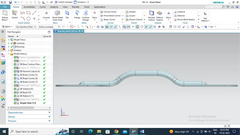
FRONT VIEW OF SHEET METAL BRACKET
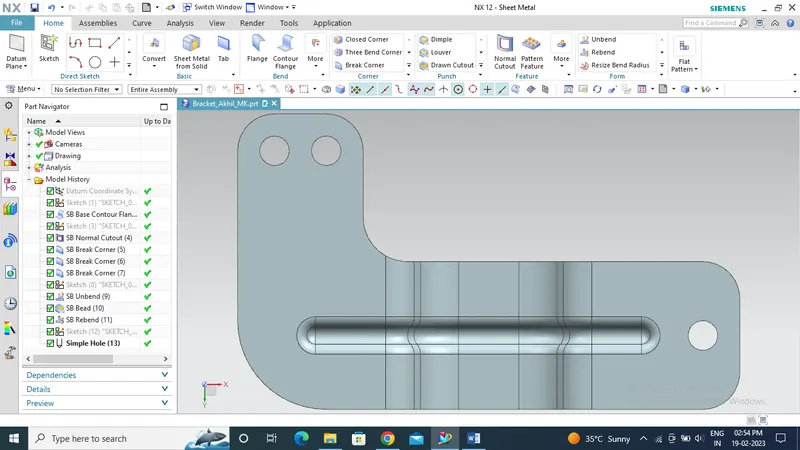
BOTTOM SIDE VIEW OF SHEET METAL BRACKET
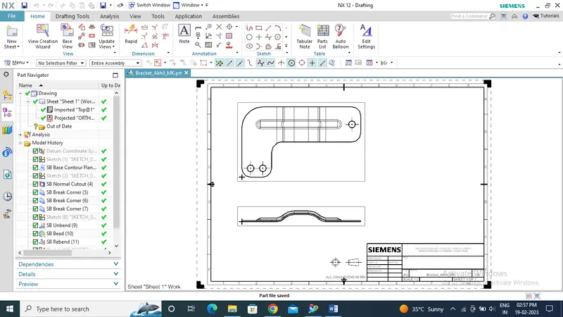
DRAFTING DRAWING OF SHEET METAL BRACKET
Conclusion
Thus an easy to manufacture, cost effective and very functional sheet metal bracket was designed and added required features by following the design guidelines and manufacturing methodologies.