Advanced Sheet Metal Design Using NX Cad Challenge_6_Bracket
BRACKET DESIGN
OBJECTIVE-
Create a Bracket design model following the given guidelines by using NX Sheet metal application.
INTRODUCTION-
Sheet metal is metal shaped by an industrial process into thin flat pieces. Sheet metal is one of the basic forms used in metalworking and can be cut and bent into various shapes.Siemens NX CAD software is a flexible and powerful integrated sheet metal modeling solution that can help us deliver better products faster and more efficiently. NX brings a new generation of design, simulation and manufacturing.
DESIGN METHODOLOGY-
DESCRIPTION-
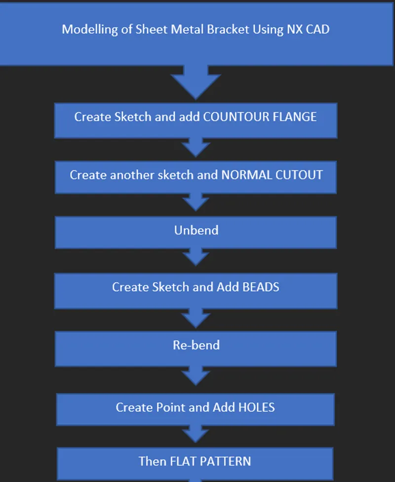
The Important tools which used during designing of Bracket are as follow.
- SKETCH-
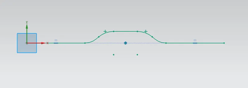
Created a Sketch in XZ plane.
- CONTOUR FLANGE-
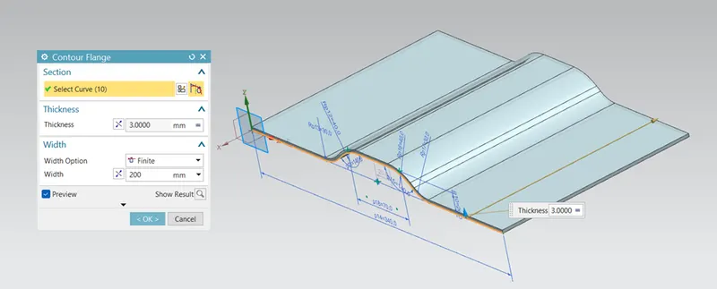
For creating a base, performed the contour flange in the sketch with thickness 3 mm and 200mm width.
- NORMAL CUTOUT-
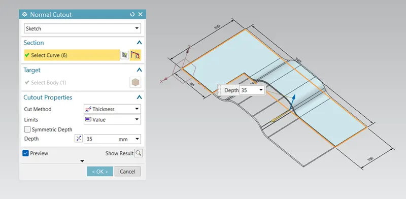
Created the sketch and performed the Normal cutout command and the cut the part as we need.
- BREAK CORNER-
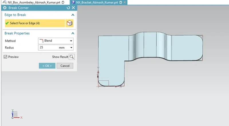
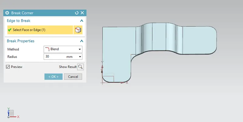
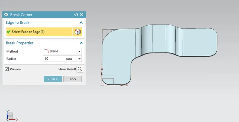
For removing the sharp corner performed the Break corner command with different values.
- UNBEND-
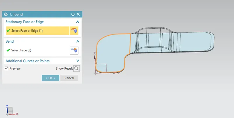
Performed the Unbend command and unbended the sheet as shown in figure for applying the feature.
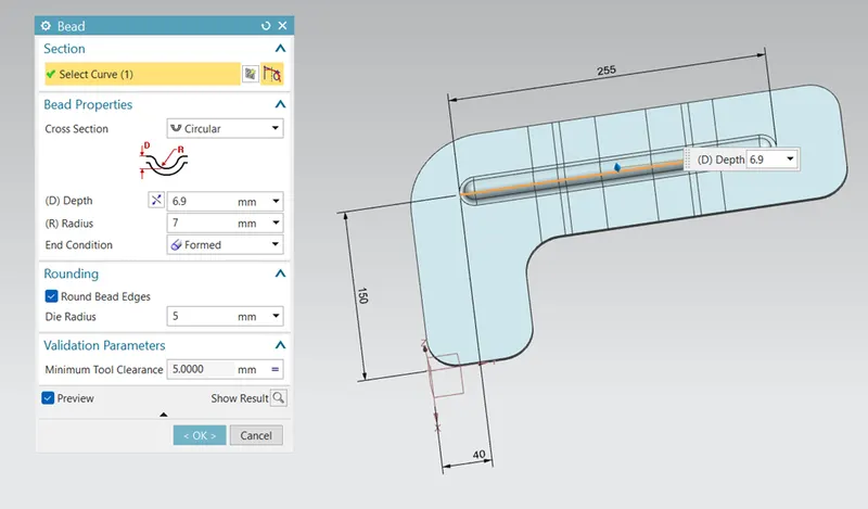
- BEAD-
For lifting the material and improve the strength of part, performed the Bead command.
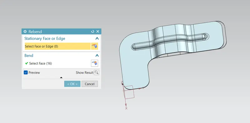
- REBEND-
Restores an unbend feature to its previous bent state, along with any features added after the unbend feature.
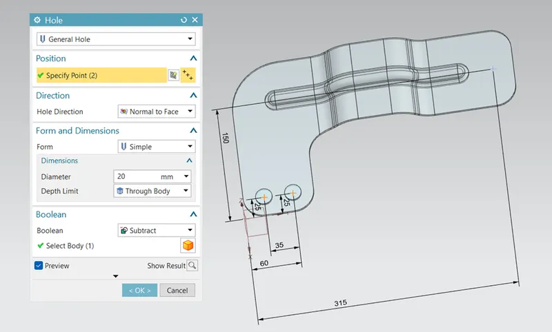
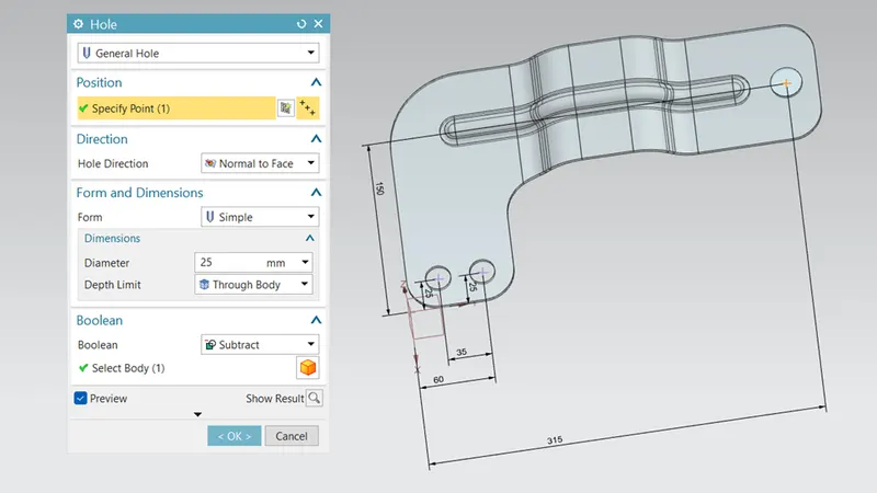
- HOLE-
For adding the hole on the part used the Hole command by creating point with given parameters as shown in figure.
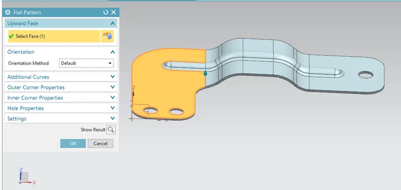
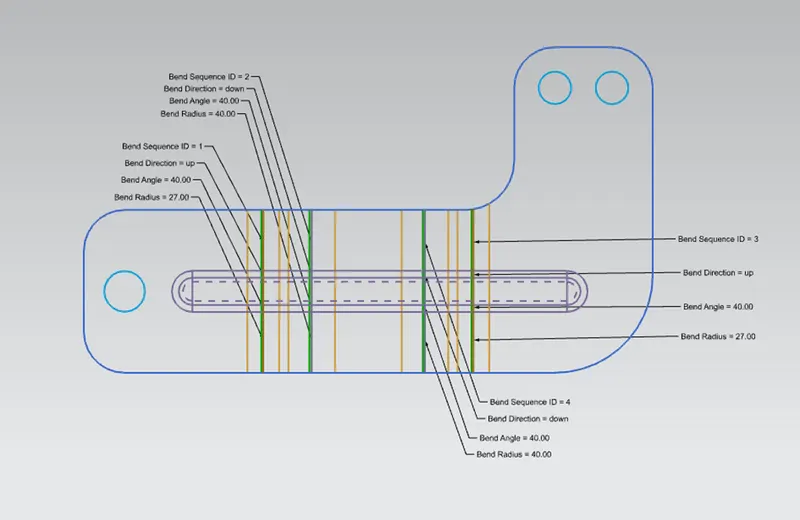
- FLAT PATTERN-
Creates a flat pattern from the formed sheet metal part.
DIFFERENT VIEWS OF MODEL-
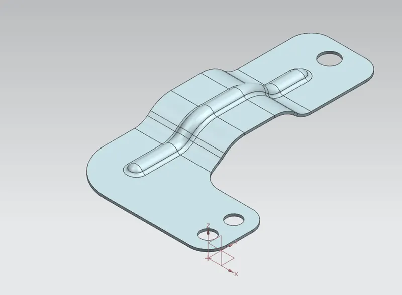
- ISOMETRIC VIEW-
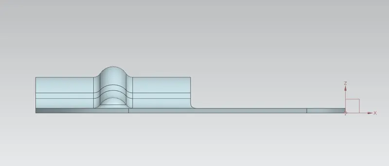
- FRONT VIEW-
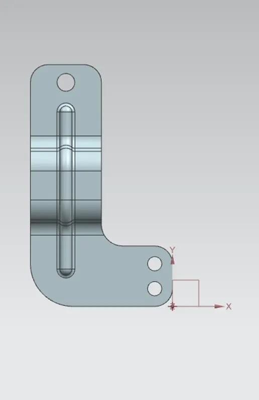
- TOP VIEW-
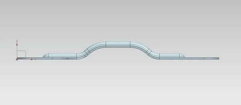
- SIDE VIEW-
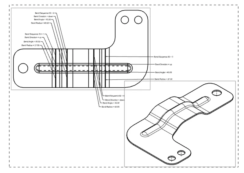
DRAFTING-
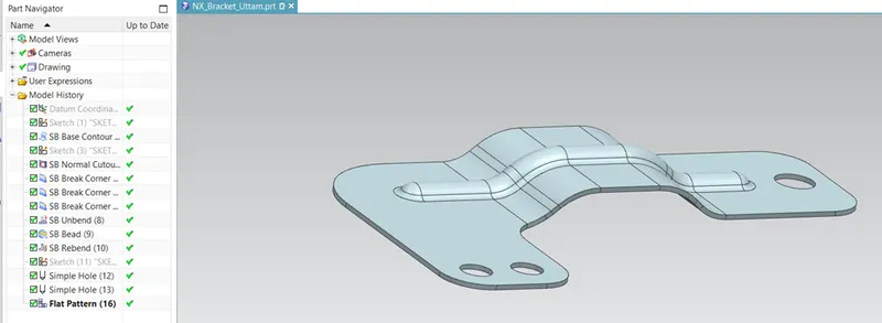
FEATURE TREE-
CONCLUSION-
In this challenge we created the sheet metal Bracket model using given guidelines. We learn about the various commands in NX Sheet metal application.