Advanced Sheet Metal Design Using NX Cad Challenge_6_Bracket
Aim : Advanced Sheet Metal Design Using NX Cad Challenge_6_Bracket
Objective :
Write a detailed report on Sheet Metal Component with good explanation on Sheet Metal modelling tools applied throughout the modelling. Also attach the Final model Images (Min. 4 images) of Sheet Metal Bracket.
Link for PDF.
https://drive.google.com/open?id=1zY8wK3FfzxTkf5n0Okg1O-y_6NVISQRb
Title of the Project : Designing of the BRACKET with sheet metal using the NX cad
Objective: The aim of this project to design a sheet metal bracket with some advanced features using NX Sheet Metal Application.
Introduction:
Nx cad software is a simple and powerful tool which has wide variety of application in various industries such as automobile , medical , aircraft etc . using the sheetmetal workbench from nx , we will create the required part The NX cad software is used to create the models and calculate the product life management PLM. So now we are using the NX cad software to design the accurate and exact cad model of the given product. byUsing features in Sheet Metal NX As Follows
Flange:- flange is used to extend the edge of the material with required angle and with required length.
Tab:-tab is normal extrude feature with thickness. It will be used to extrude the closed diagrams and linear faces.
Dimple:-Lifts an area of the model inside a sketch that simulates a stamping tool.
Bead:-Bead is similar to the dimple. Lifts and of the model along the sketch that simulates a stamping tool.
Bend:-To bend the sheet metal with some angle we will use the bend feature.
Unbend&rebend:-Unbend is used after the using of bend feature if we want create more features on the model then we need to unbend the sheetmetal.Rebend is the feature that used after the unbend of a existing model to create the final model after the features or modelling is completed.
Normal cutout:-Normal cutout is used to create the hole in flat or normal face with different closed drawings.
Hem flange:-Hem flange is similar to the flange but with folded edge to give strength to edge.
Convert from solid body to sheet metal:-This feature is used to covert the solid body into sheet metal part. By converting this model the process will be easy and convenient.
FLAT PATTERN:-Flat pattern is used to create flat pattern from formed sheet metal part.
Contour flange:-Contour flange is one type of flange that will created be the sketches on the model as per the requirement of shapes to the model.
HOLE:- This feature is used to create the hole on the model as per reequiremets
Design methodology / approach (To be explained with the help of Flowcharts only):
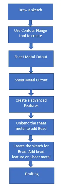
Description (Need to explain tools/ Features used while designing):
Draw Sketch:- It is a basic of any design.Drawing Tab
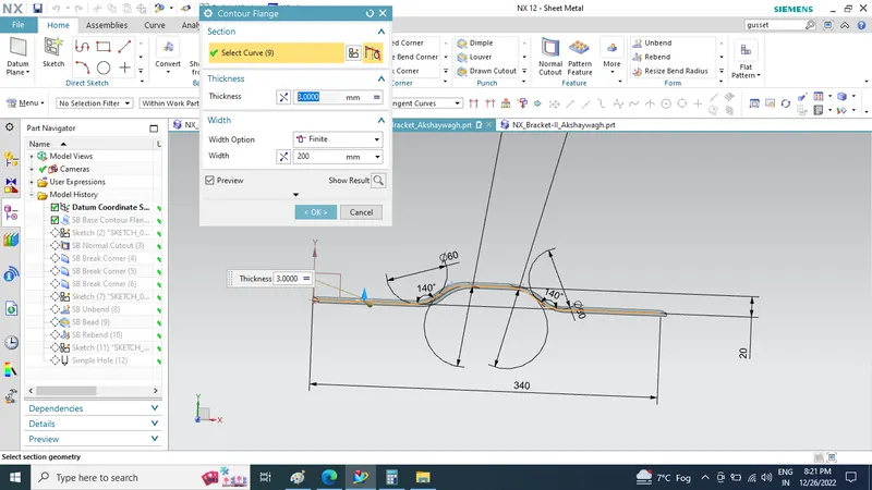
Tab:- it is used to create base feature of a sheet metal.
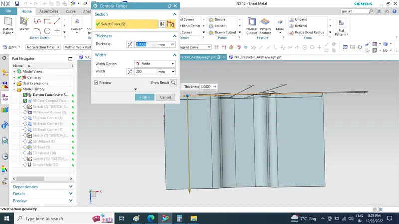
Flange:- it is used to create a extended part of a sheet metal.
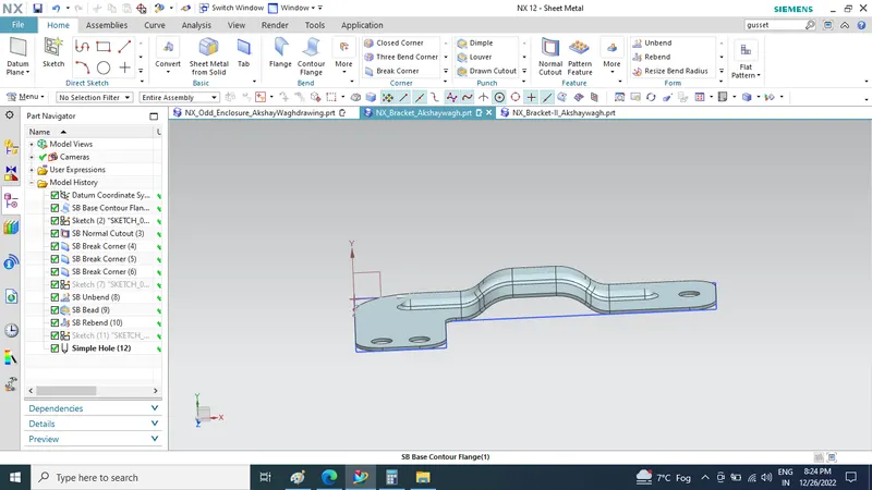
Break Corner: Break corner feature use to corner finishing of sheet metal
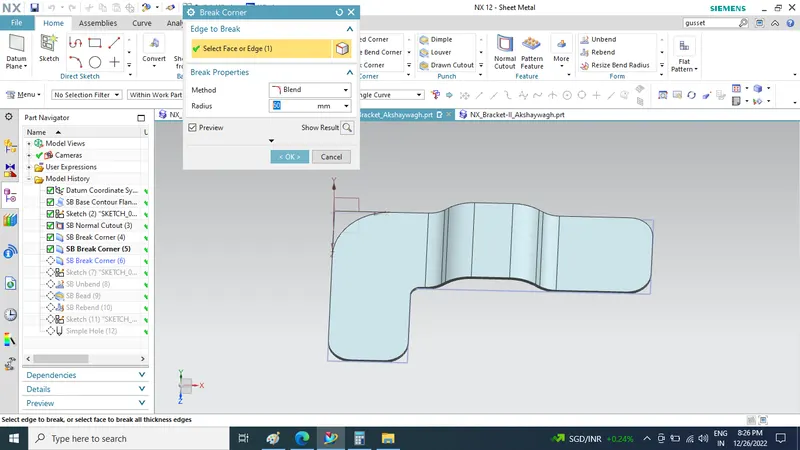
Bead: Sketch Bead on flat surface.Used for giving strength to the sheet metal.
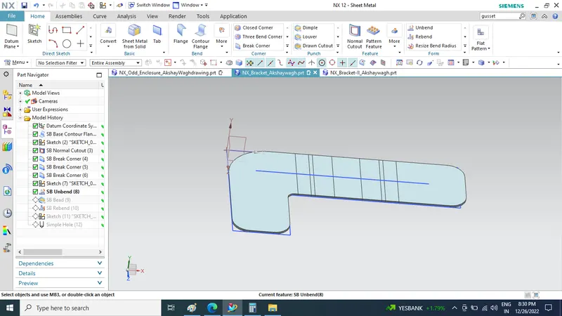
Unbend:- This feature is used to unbend the sheet metal taking any one face as a stationary face.
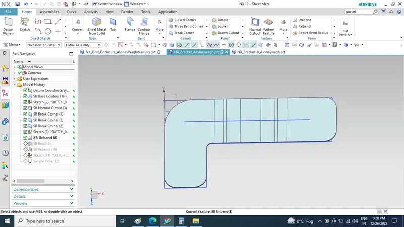
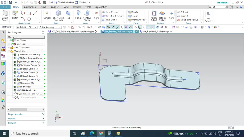
Rebend:- used to rebend the sheet metal
Simple Hole: Simple hole is created in sheet metal by sketch and then using hole feature
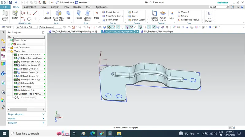
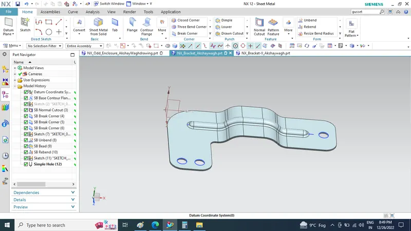
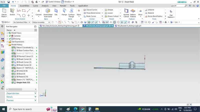
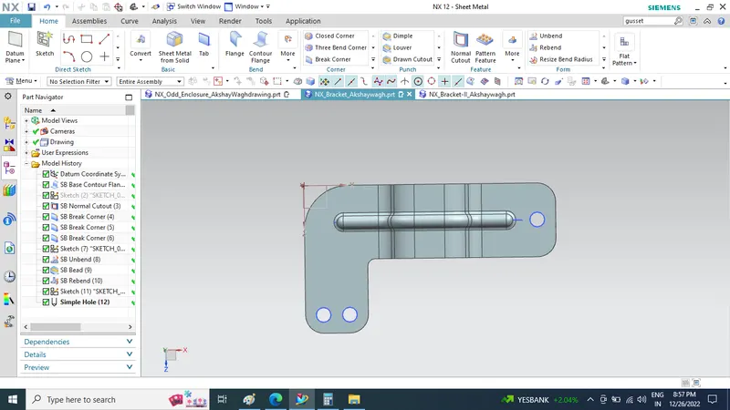
plot a min of four screenshots of Model in the report. (Front View, Side View, Isometric View and the Top View)
Isometric View
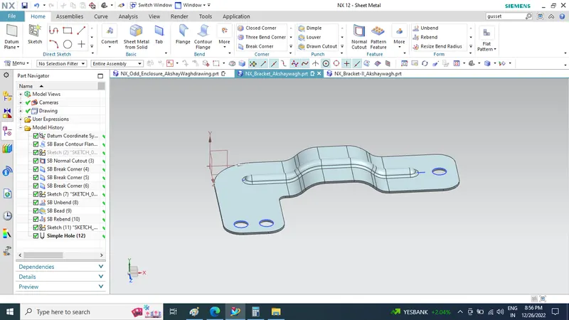
Front View
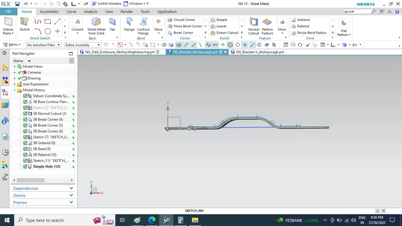
Side View
Top View
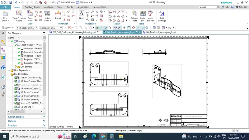
Attach Detailed Drawing Sheet Image (If Required)
Conclusion
In Siemens NX Sheet Metal Appliaction We created and learn through simple Sheet Metal bracket design with a structured design methodolgy