Advanced Sheet Metal Design Using NX Cad Challenge_6_Bracket
BRACKET
OBJECTIVE :
To observe a model and design Sheet Metal by provided dimension.
INTRODUCTION:
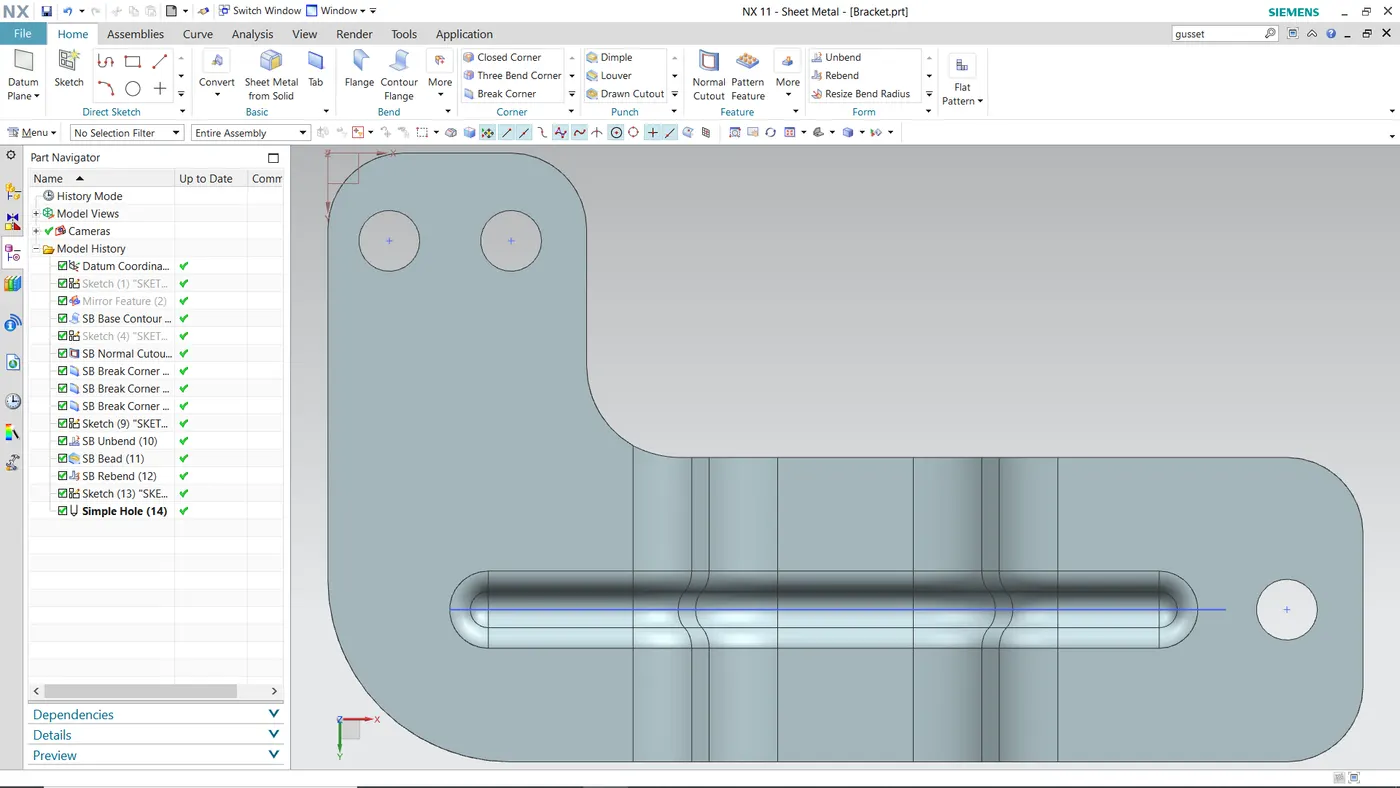
Creating “BRACKET” in NX CAD using different types of features like Flange, Advance Flange, Break Corner, Normal Cutout, Holes etc.
DESIGN METHODOLOGY:
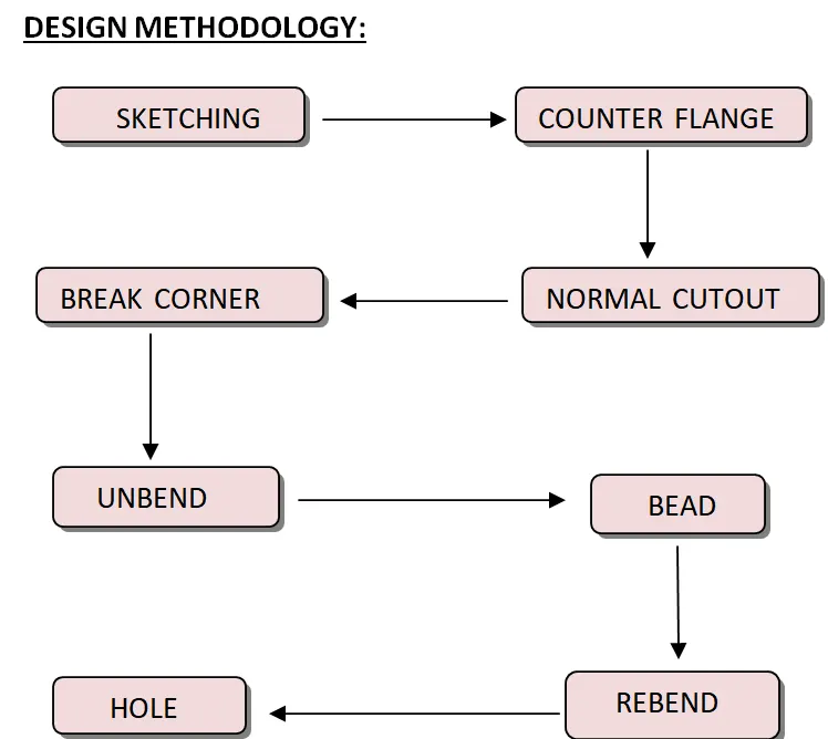 DESCRIPTIONS :
SKETCHING is used for making 2d drawings such as Line, Circle, Rectangle, Curve, Arc etc.
COUNTER FLANGE is created by extending the sketch on its respective axis with thickness as required from the base.
NORMAL CUTOUT is a command to cutout the material by projecting a sketch onto the model and then cutting perpendicular to the surfaces intersected by the projections
BREAK CORNER is a command used to round or chamfer sharp corner of a tab or flange.
HOLE is a command used to create a hole in the surface.
BEAD is a command used to lift material along the contour of sketch that simulates a stamping tool, Bread can also be created to stiffen sheet metal .
UNBEND is used to flatten the bend sheet metal to form a flat sheet. It helps in making extra features like Bead, Normal Cutout etc.
REBEND is used to make flat surface that is bend previously to do some extra feature like Hole Bead Back to its original form.
SCREENSHOTS:
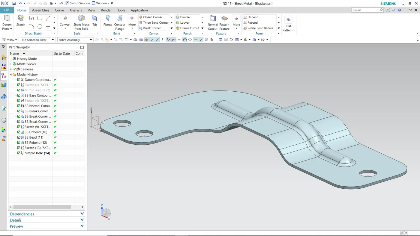
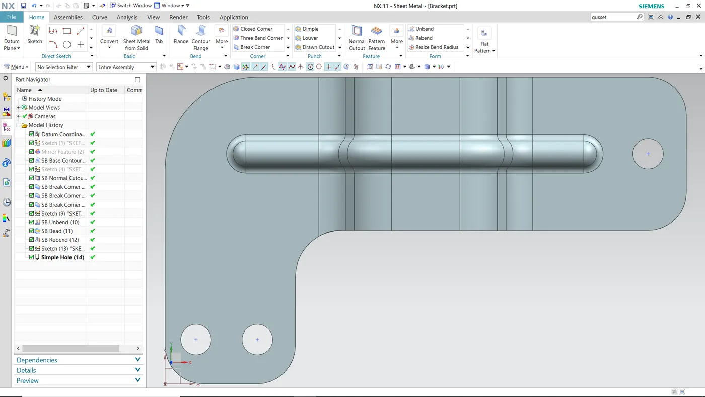
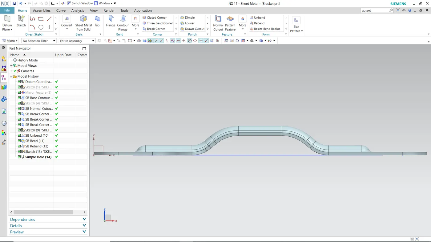
CONCLUSION:
The model has been designed and dimensioned with proper constraints.