Advanced Sheet Metal Design Using NX Cad Challenge_6_Bracket
Title of the Project : Advanced Sheet Metal Design Using NX Cad Bracket Design
Objective
The main objective of this project is to design a sheet metal BRACKET in NX cad sheet metal application workbench. Also, to perform the drafting for the bracket part.
Introduction
Software used: NX 12.0
-
To design and model the sheet metal casing in NX by using some basic features.
-
To learn to create sketches on defined planes as per requirement.
-
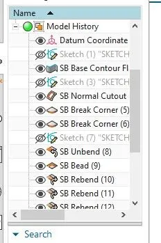
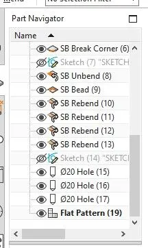
To master the user interface and basic features of Sheet metal application in NX like Tab, Flange, Break corner, Unbend, Creating holes, Re-bend, Dimple, Bead, Mirror feature, and Flat pattern.
Introduction:
Sheet metal Design and Fabrication:-
NX sheet metal design software includes material and process information in sheet metal-specific modeling features: bends, flanges, tabs, cutouts, beads, dimples, louvers, corner and edge treatments, patterns and other formable features. You can also quickly convert solid models to sheet metal components, and create sheet metal parts that enclose other components.With NX sheet metal CAD tools, you can apply standard values, such as material thicknesses and bend radii, based on industry or company best practices. With folding and unfolding capabilities, you can work with models at any stage of the fabrication process. NX sheet metal software creates accurate flat patterns for documentation and manufacturing.
Design methodology
Description:
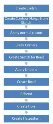
The sheet metal Bracket has been done with the above flow chart process. While designing the default thickness, bend radius relief depth and relief width value are set to 1mm at the Menu → Preferences → Sheet Metal here you can change the Sheet Metal thickness whenever necessary.
Contour flange:
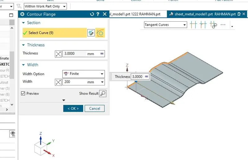
In Siemens nx sheet metal contour flange command use to create a base feature by extruding a sketch along a vector, or adds material by sweeping a sketch along an edge or chain of edge.
From the menu: Insert -> Bend -> contour flange.
Normal cutout:
Unbend:
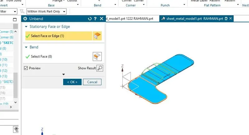
As the tool name indicates the bend tool is used to bend the sheet metal bodies and the unbend is viceversa of the bend tool,It is to unbend the bent regions.
Bead:
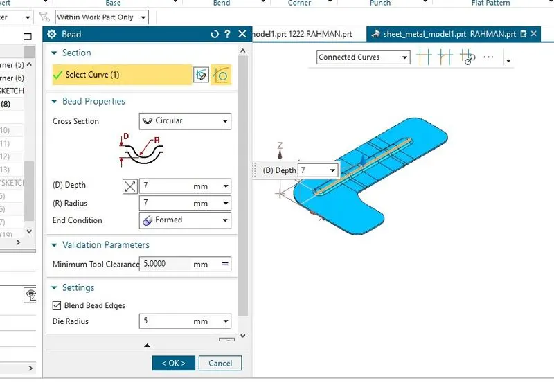
This tool is used to create a punch formation on the selected region on the body with smooth curvature on the edges.
Also we create circular projections with help of the BEAD command.
Re-bend:
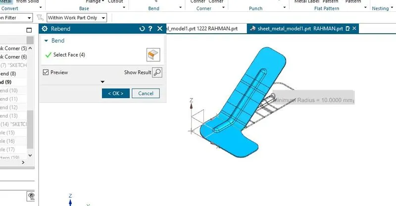
As the tool name indicates the bend tool is used to bend the sheetmetal bodies and the re-bend is viceversa of the bend tool, It is to re-bend the un-bended regions.
Simple hole:
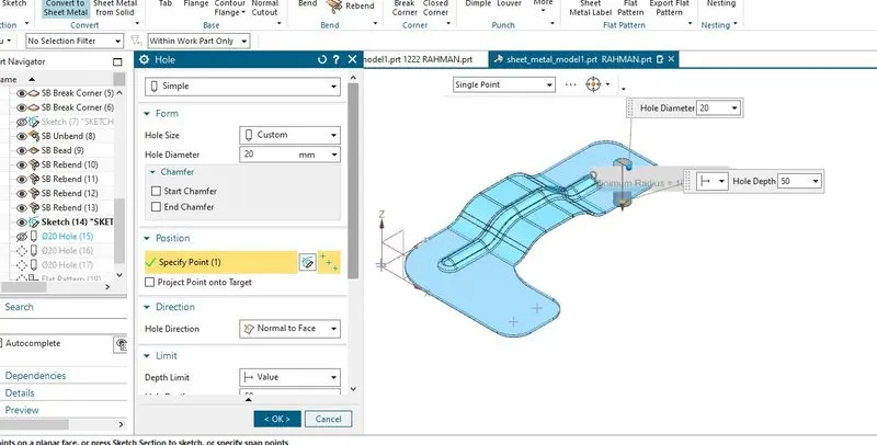
In the siemens nx modeling, hole command use to create a hole on one or more solid bodies in a part or assembly with option for counter-bored, countersunk, and threaded.
siemens nx modeling hole command make position point by point option.
siemens nx modeling hole command make position point by sketch section.
create a Simple hole in nx.
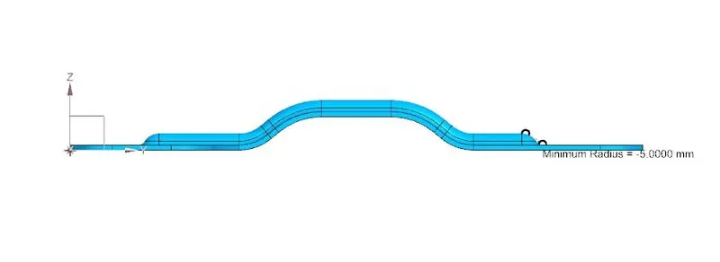
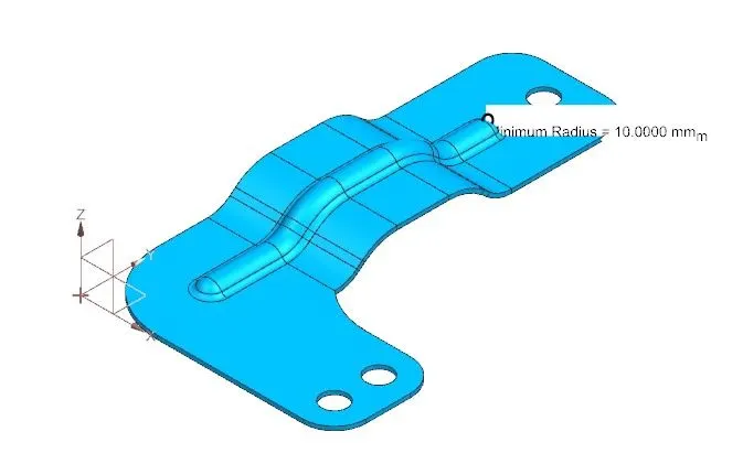
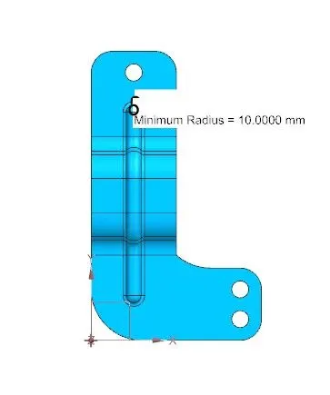
Upload a min of four screenshots of Model in the report. (Front View, Side View, Isometric View and the Top View)
Front View
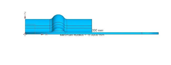
Side View
Isometric View
Top View
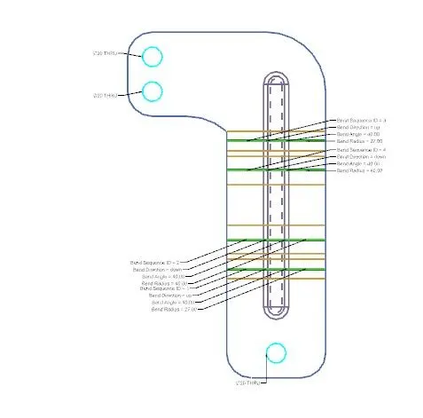
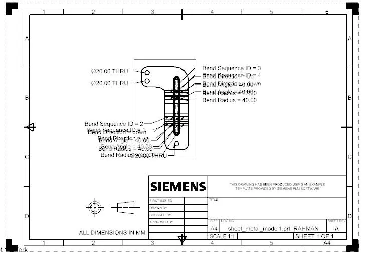
Attach Detailed Drawing Sheet Image (If Required)
Conclusion :
Designing a bracket with the sheetmetal guidelines has given a very good approach to various tools of Siemens NX that really helpful with saving time , easy to apply and update. Objectives of this project are achieved with desired result.