Advanced Sheet Metal Design Using NX Cad Challenge_6_Bracket
BRACKET
Objective : To create a Bracket with odd shapes and angles
Introduction: Brackets typically consist of two or more planes connected along one edge, and often to simplest way to fabricate this kind of object is to bend a flat object (i.e. a piece of sheet metal) in two or more places: the simplest example would be adding a 90° bend to a flat rectangle with a straight profile, turning it into a bracket with an L-shaped profile.
Design methodology / approach:
Feature tree:
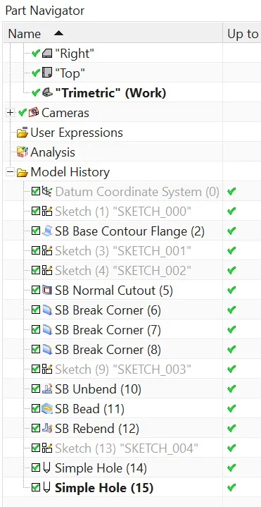
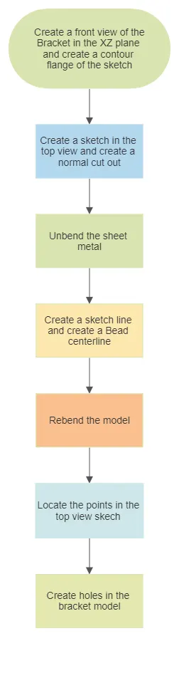
Description:
The tools used are
Datum CSYS
Sketch features: Sketch, Rectangle, Rapid Dimensioning
Sheet metal features:Contour flange, Normal cut out , Beads , Unbend , Rebend , Hole
Sketch the brackets front view
Use contour flange option to create a sheet metal from the sketch
Create another sketch in the top view and create a normal cut out
Use bead option to create a bead from the sketch line after unbending the sheet metal
Create holes in the model at particular points
Convert to sheet metal is then used to convert the solid model into sheet metal
Flanges , Jog, Bead , hole are several sheet metal features to design the model as per the requirements
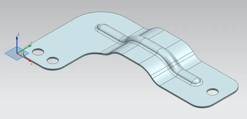
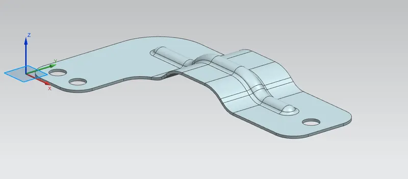
Isometric view
Side View:
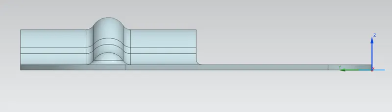
Front View:

Top View:
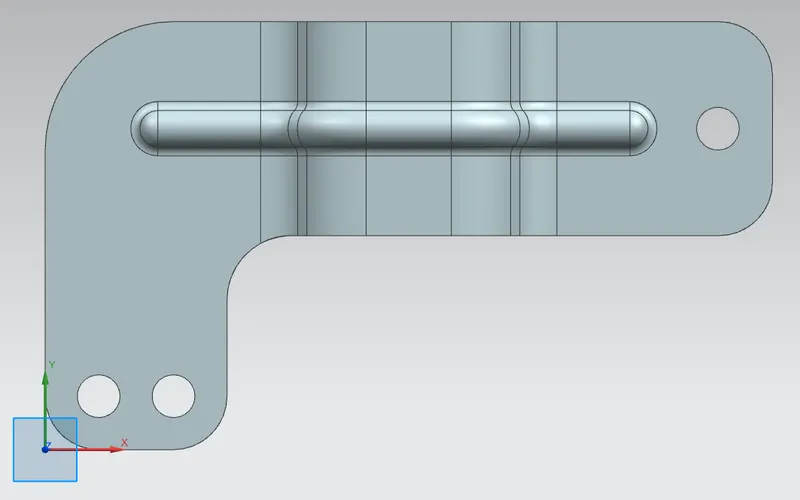
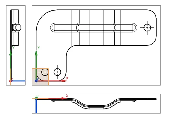
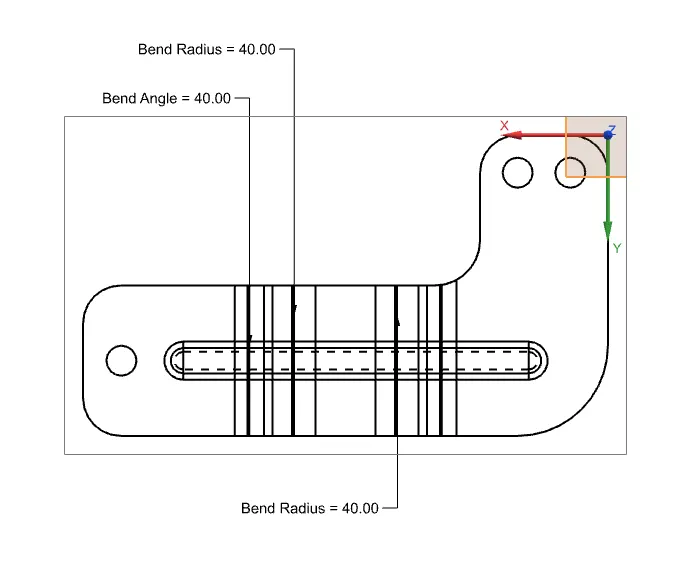
Detailed Drawing Sheet Image
Conclusion:
The bracket model is successfully created using NX cad