Advanced Sheet Metal Design Using NX Cad Challenge_6_Bracket
Designing Bracket with bead in NX
Objective: To design the sheet metal bracket with bead using NX CAD and know how to employ the various sheet metal design components required to produce sheet metal components with industrial purposes.
Introduction: Forming items from a metal sheet using punching, cutting, stamping, and bending is known as sheet metal. The longevity of sheet metal parts makes them ideal for end use applications (e.g. automotive applications). Due to high initial setup and material costs, parts used for low volume prototypes and high volume manufacturing runs are the most cost-effective. Any metal that may be shaped into flat pieces of different thicknesses is referred to as "sheet metal." Plates are thick pieces of metal. The cold-rolled steel, mild steel, stainless steel, tin, nickel, titanium, aluminium, brass, and copper are only a few of the metals used by the sheet metal industry. We use tools like Creo, NX, Catia, and other similar programmes to design the sheet metal. Straight brake sheet metal forming is the most typical, depending on the product and manufacturing process. NX Sheet Metal in the NX design environment offers a set of tools that make designing sheet metal components quick and easy. Designing a bracket, one of the sheet metal components required to suport the interior parts.
Design methodology:
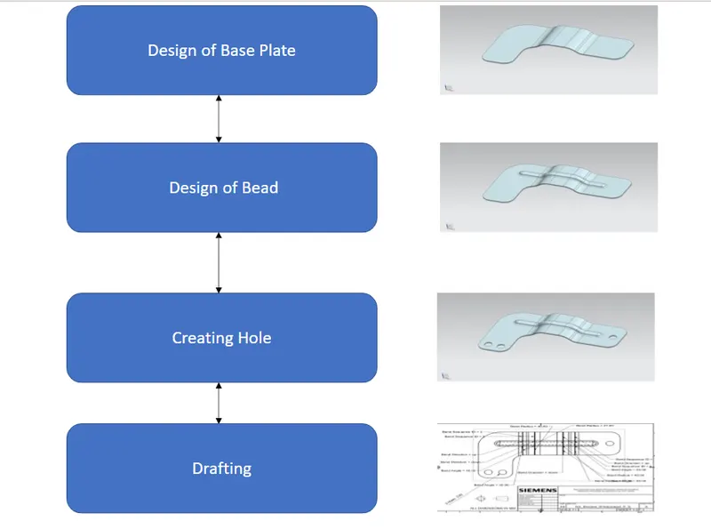
Description: Bracket Design
Step 1: Creating Base Plate
Tools Used:
Sketch: Sketch generates a 2D visual for the model when there are many sketch commands present, such as lines, rectangles, circles, etc.
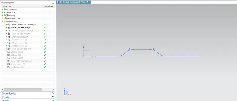
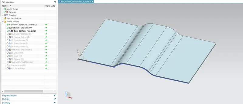
Contour Flange: extends a sketch along a vector to create a basis feature.
Sketch: Sketch generates a 2D visual for the model when there are many sketch commands present, such as lines, rectangles, circles, etc.
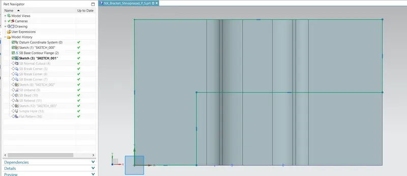
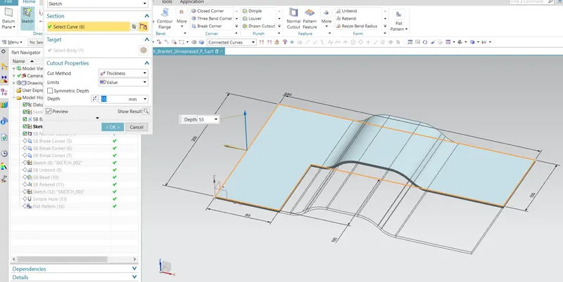
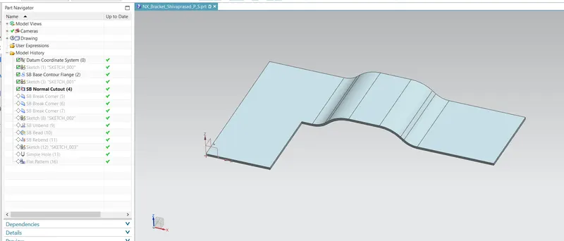
Normal Cutout: Normal Cutout commands use the principles of sheet metal manufacture to extract volumes from the sheet. Cutting faces will be parallel to the surface of the sheet metal.
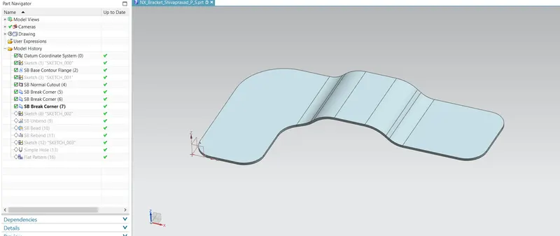
Brake Corner: It is the tool used to chamfer and round the Sharp edges.
Step 2: Creating Bead and Holes On Base Plate
Tool Used:
Sketch: Sketch generates a 2D visual for the model when there are many sketch commands present, such as lines, rectangles, circles, etc.
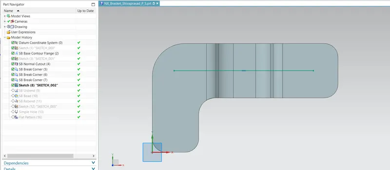
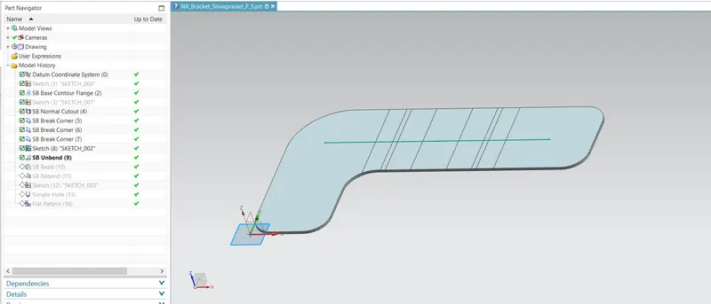
Unbend: Bent metal can be flattened with this feature. To add features to the bent part, we must unbend the body.
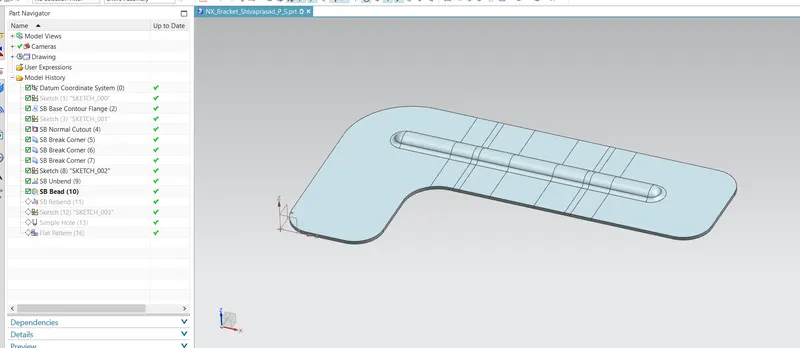
Bead: lifts materials in a stamping-like motion along the outline of a sketch.
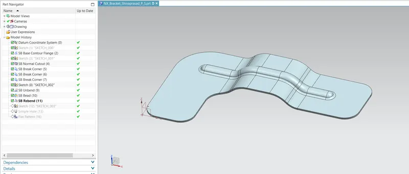
Rebend: The feature is then returned to its initially bent state after the characteristics have been added.
Point: Points to creat a featues.
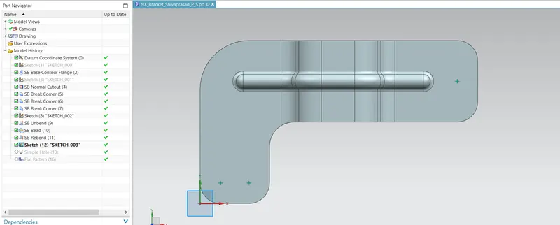
Hole: On the sheet metal model, holes of various shapes are made using hole.
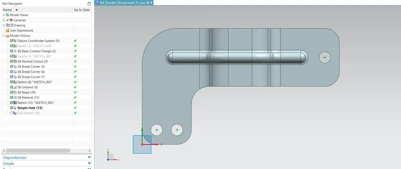
Flat Pattern: A flattened pattern of the sheet metal item is made to be used in drafting.
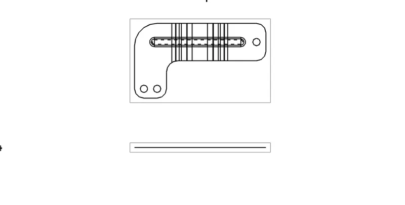
Views:
Isometric Views:
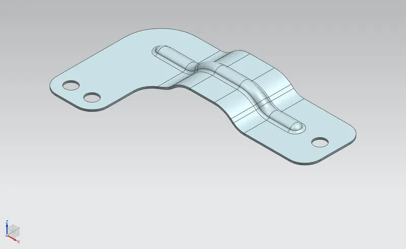
Front Views:
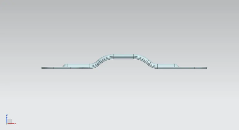
Left Views:
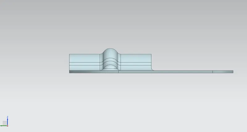
Right Views:
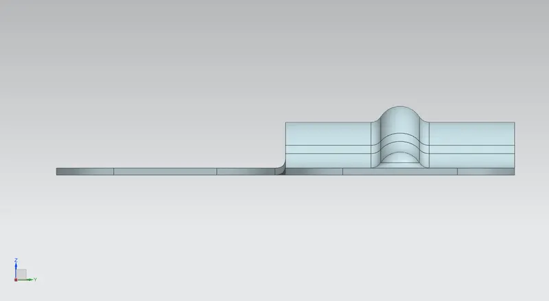
Top Views:
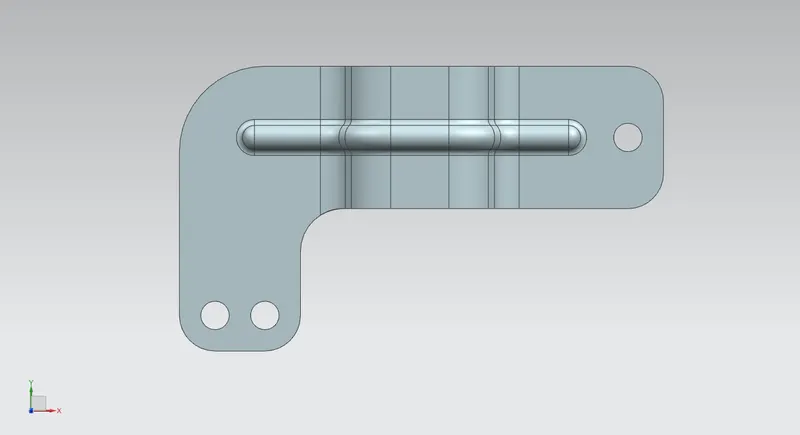
Drafting View:
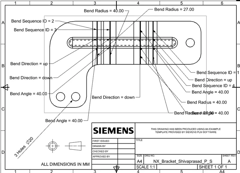
Conclusion: As a result, the braket design is produced using NX with the required dimensions.