Advanced Sheet Metal Design Using NX Cad Challenge_6_Bracket
BRACKET DESIGN IN NX CAD
Objective:-
To design a Bracket by using Siemens NX12 Sheet metal application.
introduction
The NX cad software is used to create the models and calculate the product life management PLM. So now we are using the NX cad software to design the accurate and exact cad model of the given product.
Design methodology:-
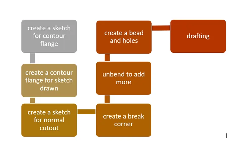
Description:
The sheet metal Create ‘Bracket’ from the 2d Drawing has been done with the above flow chart process. In the NX Cad using default thickness, bend radius, relief depth & width values are set to 3 mm
2D Sketch:
2D Sketching in Drawings. You can create drawing geometry using 2D sketched geometry only, without reference to existing models or assemblies. ... When you drag a sketch point in a drawing, it snaps or infers to other sketches, drawing views, blocks, and items in the sheet format
Contour flange:
Creates a base feature by extruding a sketch along a vector, or adds material by sweeping a sketch along an edge or chain of edges.
2D Sketch:
2D Sketching in Drawings. You can create drawing geometry using 2D sketched geometry only, without reference to existing models or assemblies. ... When you drag a sketch point in a drawing, it snaps or infers to other sketches, drawing views, blocks, and items in the sheet format.
Normal Cut out:
The command is used to cut the material on the exists sketch on the plane.
Break corners:
This command is used to create the round/fillet the sharp corners.
Unbend:
This command is used to unbend the sheet metal. The punching & drilling operation can be performed by only flat planes only.
Bead:
This command is used to create a long drawn out impression ,which is impressed to increase the stiffness in the sheet metal part.
Re-bend:
After finish all these operations then we should to re-bend the un-bended parts.
Holes:
In the Hole feature we can select the points and type requirement we need it.
Flat pattern:
This is used to create the flattened sheet and prepare the model of manufacturing process.
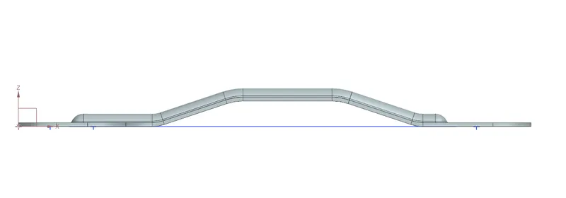
front view:
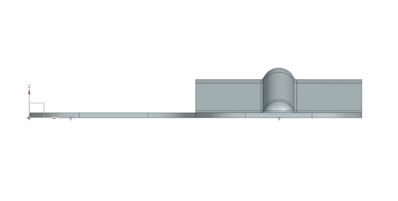
side view:
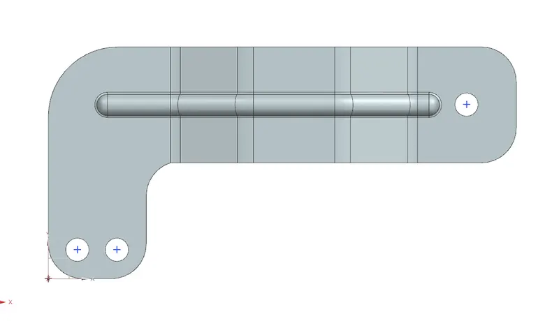
top view:
isometric view:
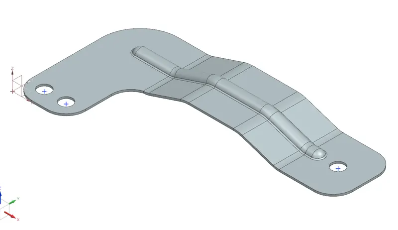
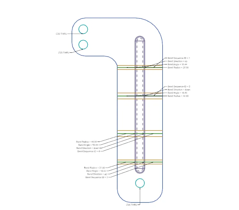
detailed drawing
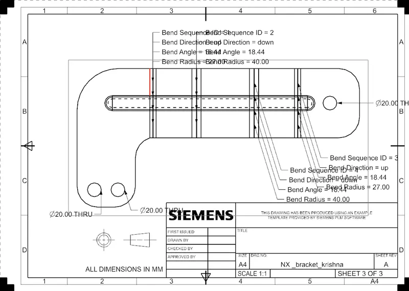
Conclusion:
The sheet metal Create ‘Bracket’ from the 2d Drawing is successfully completed in NX Cad.