Advanced Sheet Metal Design Using NX Cad Challenge_6_Bracket
BRACKET DESIGN IN NX CAD
Objective
Designing of the BRACKET with sheet metal using the NX cad
The NX cad software is used to create the models and calculate the product life management PLM. So now we are using the NX cad software to design the accurate and exact cad model of the given product.
Design methodology:-
- Open new sheet metal part in NX cad
- Create contour flange using sketch with given parameters
- Cut the body using normal using given dimensions
- Give some break corners with required dimensions
- Unbend the model and create bead with using line sketch
- Create some holes as per requirements
- Rebend the model
- If required create the drawing sheet using draft tool for understanding to customer
- Hence the model is ready
Description
Flange:-
flange is used to extend the edge of the material with required angle and with required length.
Tab:-
tab is normal extrude feature with thickness. It will be used to extrude the closed diagrams and linear faces.
Dimple:-
Lifts an area of the model inside a sketch that simulates a stamping tool.
Bead:-
Bead is similar to the dimple. Lifts and of the model along the sketch that simulates a stamping tool.
Bend:-
To bend the sheet metal with some angle we will use the bend feature.
Unbend&rebend:-
Unbend is used after the using of bend feature if we want create more features on the model then we need to unbend the sheetmetal.
Rebend is the feature that used after the unbend of a existing model to create the final model after the features or modelling is completed.
Normal cutout:-
Normal cutout is used to create the hole in flat or normal face with different closed drawings.
Hem flange:-
Hem flange is similar to the flange but with folded edge to give strength to edge.
Convert from solid body to sheet metal:-
This feature is used to covert the solid body into sheet metal part. By converting this model the process will be easy and convenient.
FLAT PATTERN:-
Flat pattern is used to create flat pattern from formed sheet metal part.
Contour flange:-
Contour flange is one type of flange that will created be the sketches on the model as per the requirement of shapes to the model.
HOLE:- This feature is used to create the hole on the model as per requirements
Images
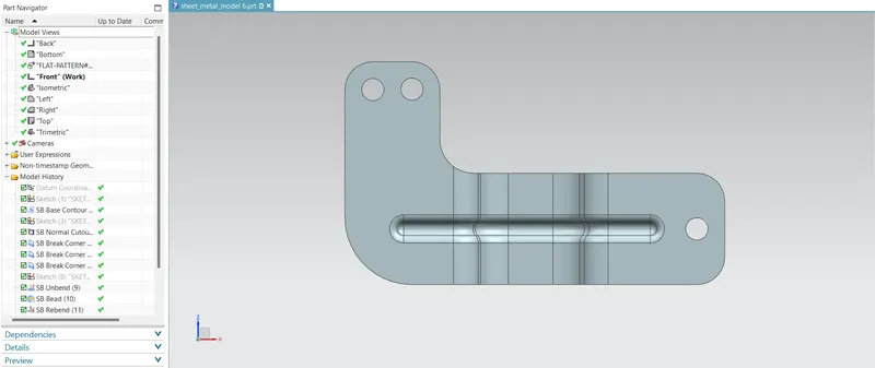
Front View
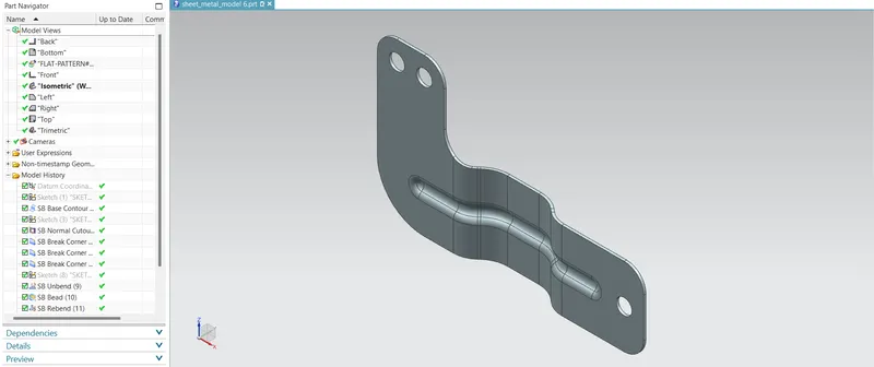
Isometric View
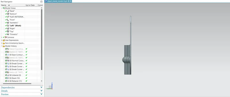
Side View
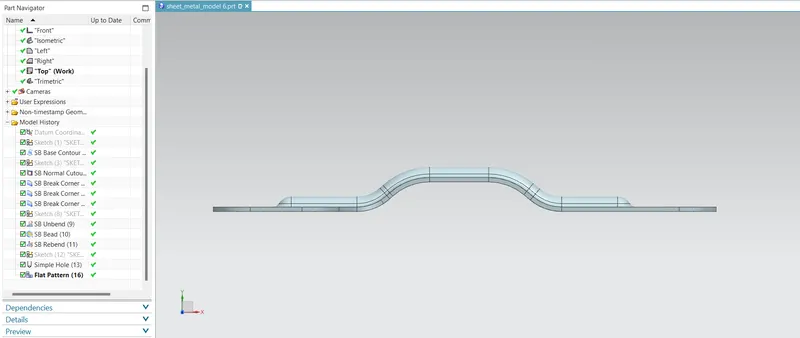
Top view
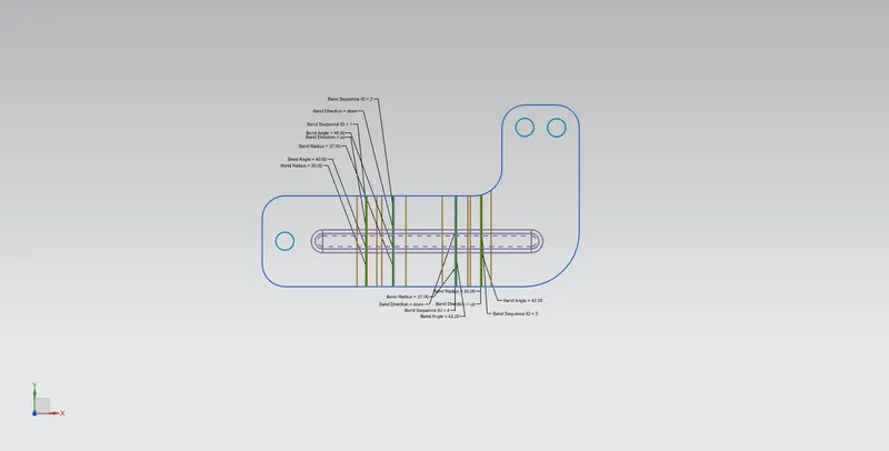
Drawing Sheet Image
Conclusion:-
Bracket is obtained using basic feature of sheet metal application.