Advanced Sheet Metal Design Using NX Cad Challenge_6_Bracket
BRACKET DESIGN IN NX CAD
OBJECTIVE
To design a sheet metal Bracket by using siemens NX cad software
INTRODUCTION
Sheet metal is metal formed by an industrial process into thin, flat pieces. Countless everyday objects are fabricated from sheet metal. Thicknesses can vary significantly; extremely thin sheets are considered foil or leaf, and pieces thicker than 6 mm (0.25 in) are considered plate steel or "structural steel".
We can also quickly convert solid models to sheet metal components, and create sheet metal parts that enclose other components.
NX Sheet Metal provides a set of tools within the NX design environment that allows for simple and fast design of sheet metal parts, dependent on their material and manufacturing process, the most common of which is straight brake sheet metal forming.
NX sheet metal design software incorporates material and process information in sheet metal-specific modelling features: bends, flanges, tabs, cutouts, beads, dimples, louvers, corner and edge treatments, patterns and other formable features.
NX Sheet Metal-specific features such as flanges, tabs, jogs, corner conditions, and drawn cutouts & many more along with productivity enhancements such as - automatic bend reliefs.
So, in this project I am going to design a Bracket by using sheet metal tools and commands.
METHODOLOGY
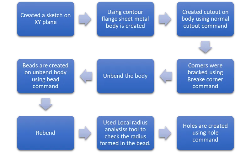
DESCRIPTION
- SKETCHING -
Making a 2d drawing such as curves, arcs, circles, points, rectangles and many options to create features for upcoming designing.
- COUNTER FLANGE
It is created by extending the sketch on its respective axis with thickness as required from the base.
- NORMAL CUTOUTS -
It is used to create a cutout on the sketch where there is a requirement.
- BREAK CORNERS -
This feature is used to create radius at the corners in order to make the corner smooth.
- UNBEND -
It is to flatten the bend sheet metal to form a flat sheet. It helps in making a extra features like bead, normal cutout on the sheet metal after bending.
- BEAD -
This is to create a counter shaped accordingly to their sketch in the reruired direction with required punch/die radius.
- REBEND -
It is to make flat surface that is bend previously to do some extra features like holes, bead back to its original form.
- HOLE
It is to create a hole on sketch, or to create a counter bored, counter sink and several hole options to do.
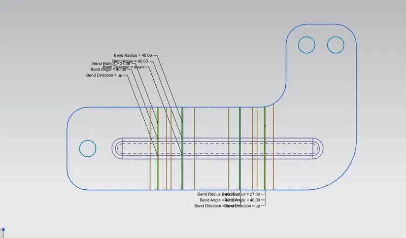
- Flat Pattern
Flat pattern is the representation of the entire sheet metal component in the 2D form with all the bends, cutouts, holes and additional features in the form of lines or edges. The flat pattern ensures the ability to cut the sheet metal out of the raw sheet metal plate. It removes the possibility errors such as interference or collision within the same component.
- Local Radius analysis
To measure radii formed in sheet metal.
VIEWS
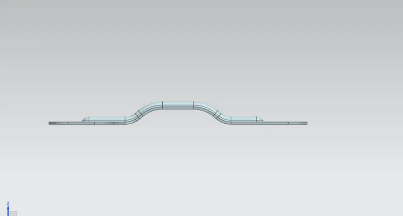
Front view
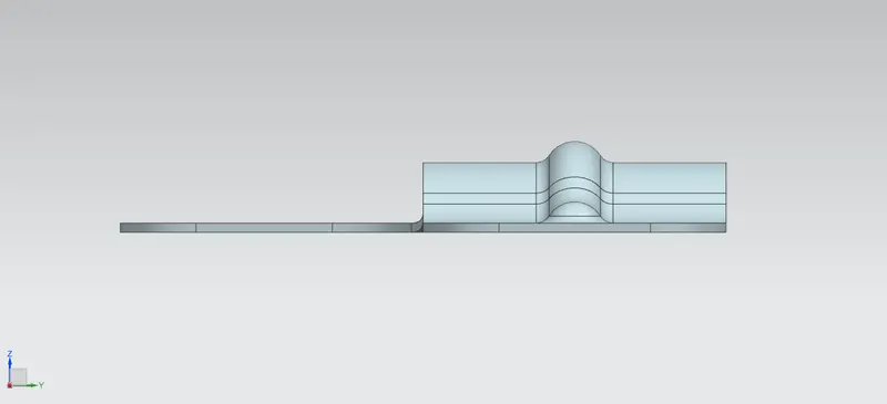
Side view
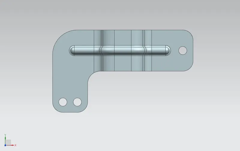
Top view
Isometric view
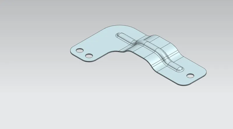
Flat pattern
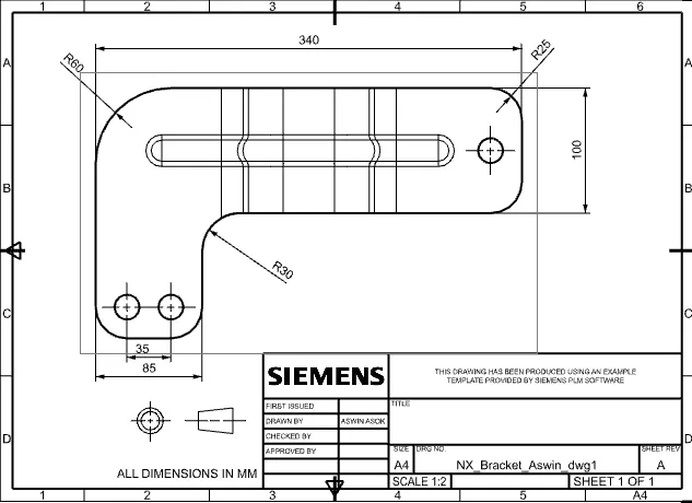
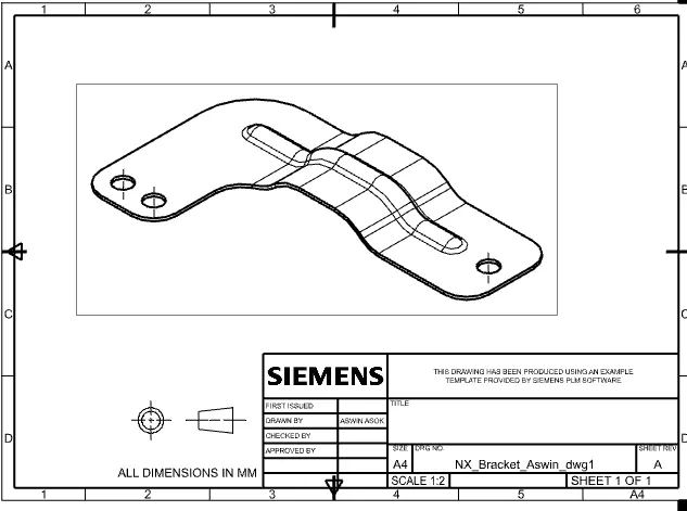
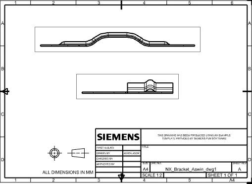
Drawing sheet
CONCLUSION
Learned how to create a sheet metal bracket using various features such as contour flange, bead, hole, normal cutout, etc from a 2d detailed drawing sheet.