Advanced Sheet Metal Design Using NX Cad Challenge_6_Bracket
Bracket Design using NX
Objective
To design a bracket in sheet metal application and to draft the model in NX and learn different features used in sheet metal.
Introduction
Sheet Metal can be defined as the metal which is thin in thickness, generally ranging between 0.6mm to 6mm. Sheet Metal are generally of uniform thickness sheets.
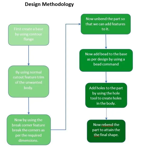
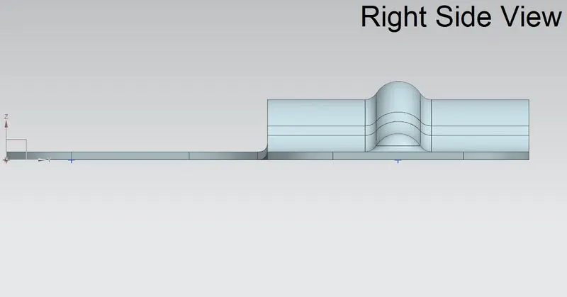
In this challenge we have designed a bracket using various sheet metal tools such as contour flange, normal cutout, break corner, unbend, bead, rebend, etc.
Description
- Sketch
Sketch is a tool used to draw a 2d model so that we can convert the 2d model into the 3d model by using the sketch references.
- Contour Flange
Contour Flange can be defined as a tool which is used to add multiple flanges on the base part. To create a flange, we need a base part.
- Normal Cutout
Normal Cutout is a feature used to trim out the unwanted body.
- Break Corner
Break Corner is a tool used to break the corner i.e., add fillet on the edges to smoothen the sharp edges.
- Unbend and Rebend
Unbend tool is used when we want to unbend the bended regions. Rebend feature is used when we want to rebend the unbended regions by simple selecting a base face as reference and then selecting face that we want to rebend.
- Bead
This tool is used to create bead feature on the part by selecting the curve created in a sketch tool. It lifts the material along the selected sketch and creates a bead with selected cross section like circular, U-Shaped, V-Shaped.
- Hole
Hole is a command as name suggests is used to create holes on the part by giving the sketch as input for the location of hole.
- Flat Pattern
Flat pattern is a feature used to flatten out the formed sheet metal.
- Drafting
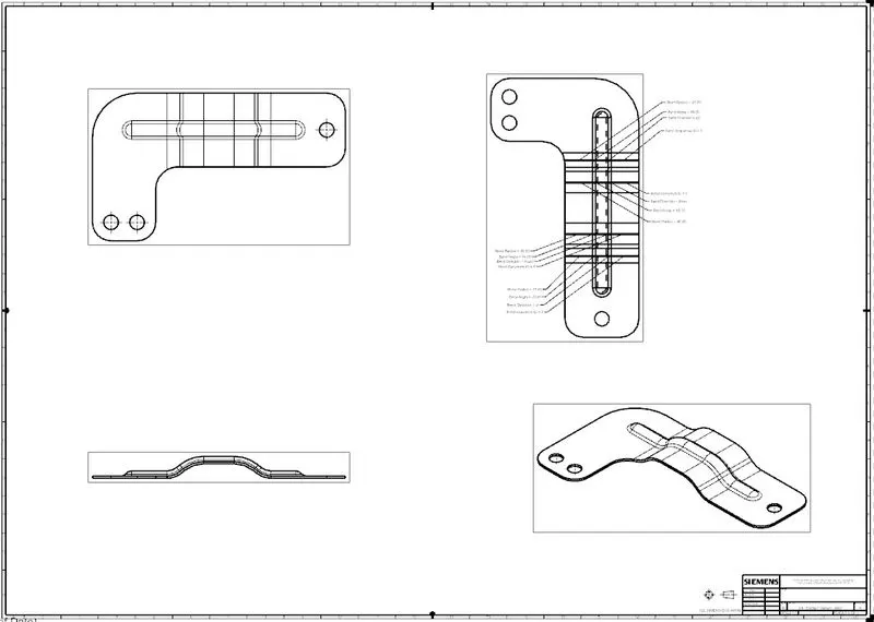
Once the modelling part is done then drafting tool is used to create detailing drawings of the part.
Conclusion
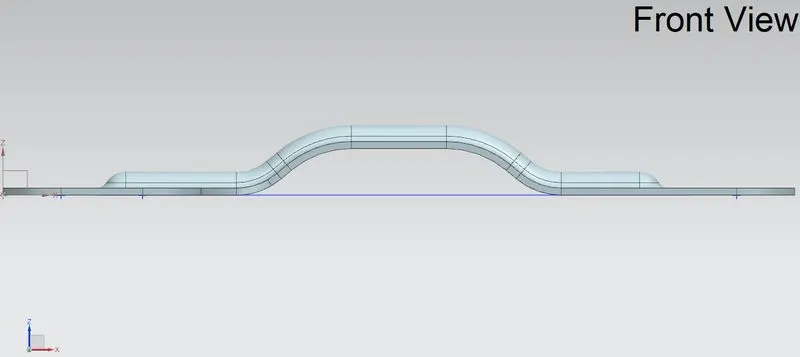
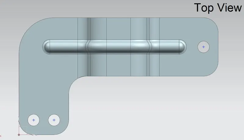
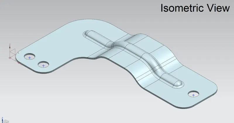
We have successfully learned and created a Bracket in sheet metal design and drafting.