Advanced Sheet Metal Design Using NX Cad Challenge_2_Box Assembly
Box Assembly Design using NX
Objective
To design the box assembly in sheet metal application and to draft the model in NX and learn different features used in sheetmetal.
Introduction
Sheet Metal can be defined as the metal which is thin in thickness, generally ranging between 0.6mm to 6mm. Sheet Metal are generally of uniform thickness sheets.
In this challenge we have designed a box assembly using various sheet metal tools such as tab, bend, unbend, flange, hem flange, mirror feature, dimple, etc.
Design Methodology
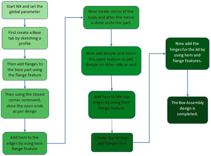
Description
- Sketch
Sketch is a tool used to draw a 2d model so that we can convert the 2d model into the 3d model by using the sketch references.
- Tab
Tab can be defined as the base part of the sheetmetal. Tab is formed when a sketch is provided. Tab can also be designed as a secondary
- Flange
Flange can be defined as a tool which is used to add flange on the base part. To create a flange, we need a base part.
- Closed Corner
Closed corner is a command which is used to close the corners of the edges by selecting adjacent bends.
- Hem Flange
Hem Flange is used when we want apply the hem on the edges by selecting the edge.
- Mirror and Unite
Mirror feature is used to mirror the selected part about a plane, whereas unite is used to merge the two parts as a single part.
- Dimple
This tool is used to create a dimple on the flat part. We can control the dimple by toggling the direction of dimple, punch radius, depth, etc. to control the result.
- Unbend and Rebend
Unbend tool is used when we want to unbend the bended regions. Rebend feature is used when we want to rebend the unbended regions by simple selecting a base face as reference and then selecting face that we want to rebend.
- Bead
This tool is used to create bead feature on the part by selecting the curve created in a sketch tool.
- Break corner
Break corner is used when we want to smooth the sharp corners. Break corner simple smoothens the sharp corners
- Cutout
Cutout is a tool which is used to remove the metal from the part.
- Drafting
Once the modelling part is done then drafting tool is used to create detailing drawings of the part.
Conclusion
We have successfully learned and created a box assembly casing sheet metal design and drafting.
Model Images
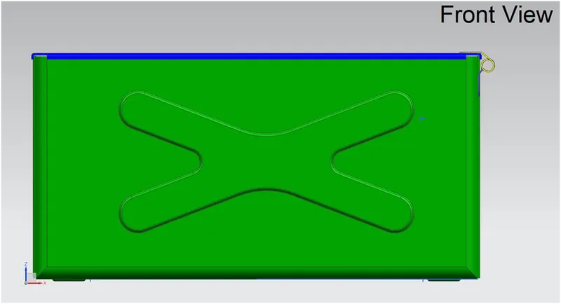
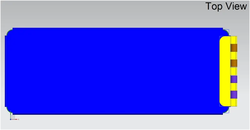
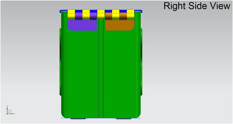
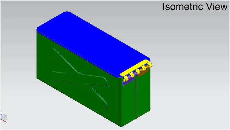
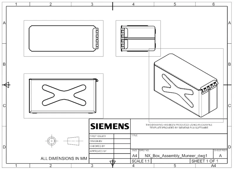
Screenshots of model in different views and screenshot of drawing of the model