Advanced Sheet Metal Design Using NX Cad Challenge_6_Bracket
Bracket Design Report
Objective:
To design the bracket by using the sheet metal application (NX 12.0).
Introduction:
NX CAD is the most powerful used in Designing software, flexible, and innovative product development solution in the industry. NX used for Design has the features, performance and capabilities to help you get the product to market faster than ever before. Designing software used for multi-purposes such as designing, Drawing engineering and manufacturing. It is used in various fields for different types of work. Using various features and methods we have designed here
Design Methodology:
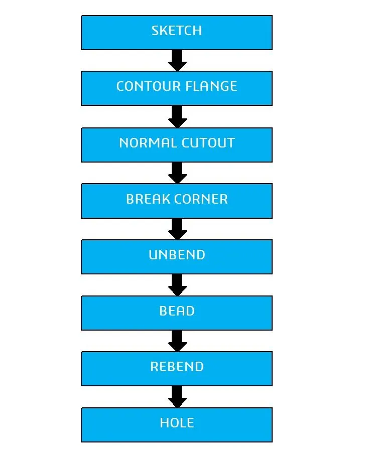
This design considers the features such as Contour Flange, Unbend, Normal Cutout, Break Corner, Bead, Rebend, Hole, Flat Pattern and Drafting. The design methodology used for this challenge can be summarized as depicted in the flowchart mentioned above image.
Feature Description:
Contour Flange:
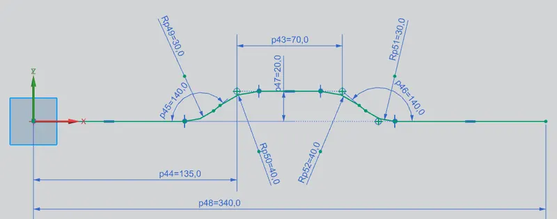
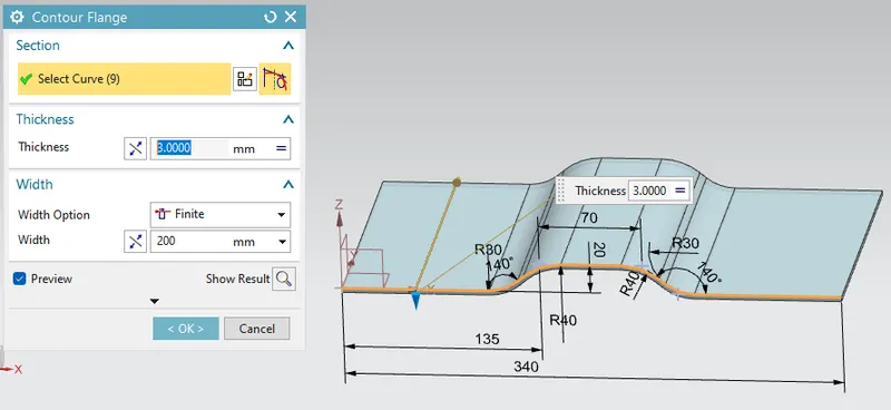
- It is used to make contour flange by using the 2d sketch.
- I created a contour flange with a length of 200 mm normal to the XY plane
Unbend:
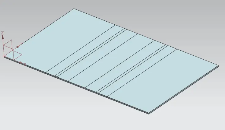
- Unbend is a very useful tool in the NX-CAD. In the Unbend dialogue box, select as stationary face the larger horizontal face of the metal sheet.
- It is used to unbend on the solid body.
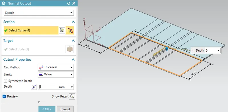
Normal Cutout:
- A sketch is created on the XY plane to cut the unnecessary portion.
- Normal Cutout is used to remove the unwanted material.
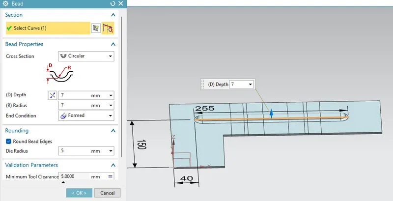
Bead:
- Bead is created to shape according to the sketch in the required direction with a required punch.
- It is used to make bends on surfaces.
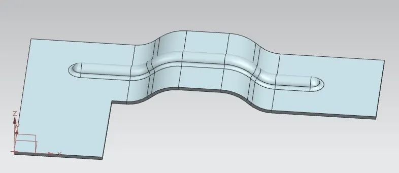
Rebend:
- It is used to make an original shape to a sheet metal body by using the rebend.
- Rebend is used to bend from the unbend parts.
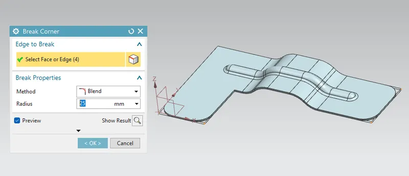
Break Corner:
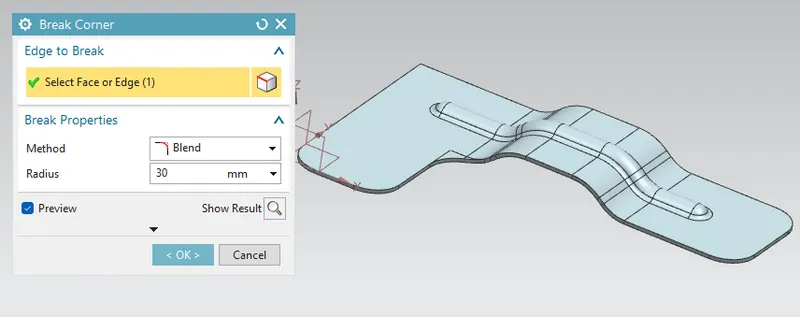
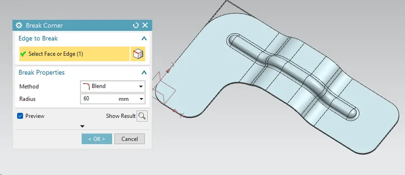
- The break corner feature breaks the sharp edge in the corner and makes it round.
- Break corner helps to prevent stress relief and fracture breaking and make the smooth corner.
- It is used to avoid the crushing force of accidents due to sharp corners.
Hole:
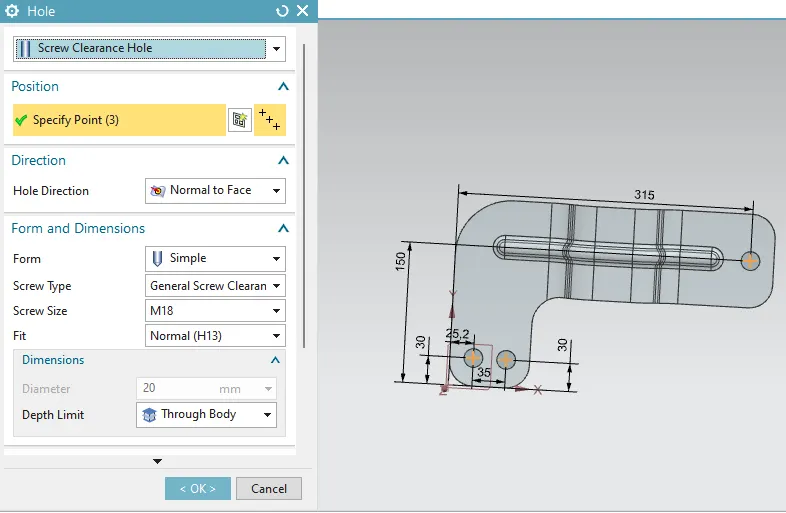
- The hole can be created simple, with a screw clearance hole and a fit.
- set the depth limit option to through the body.
- It is used to create a hole in the sheet metal body.
Measure Distance:
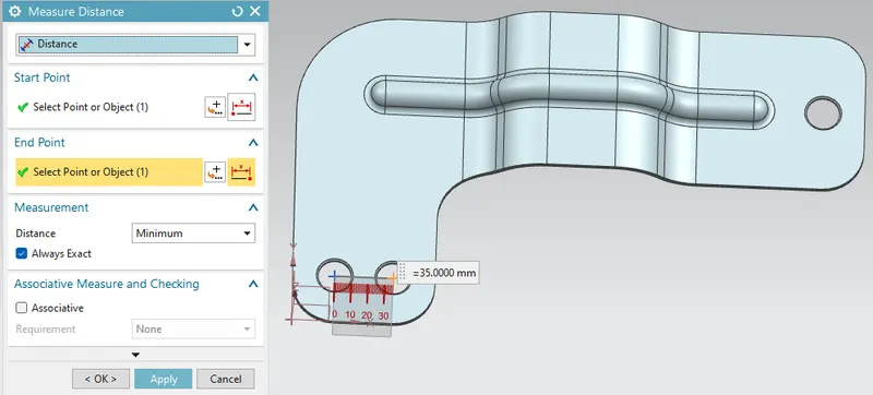
- This tool allows for measuring the distance between the two holes in the bracket part as shown in the below image.
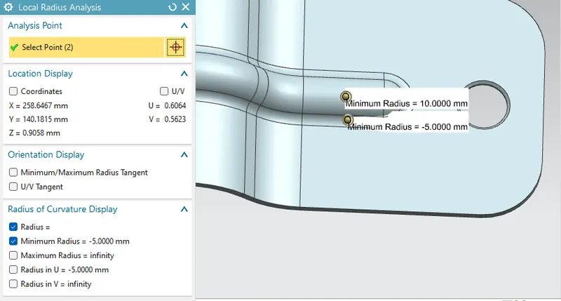
 Local Radius Analysis:
- In NX-CAD the radius value of the parts and models can be easily measured or analyzed by using the local radius tool under the tab " Analysis ".
- The local radius of the bead and bend radius is measured as shown in the below image.
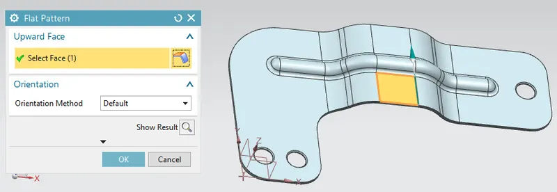
Flat-Pattern:
- Select the central face of the metal sheet and validate.
- Flat-pattern is the representation of the entire sheet metal component.
- It removes the possible such as interference or collision within the same component
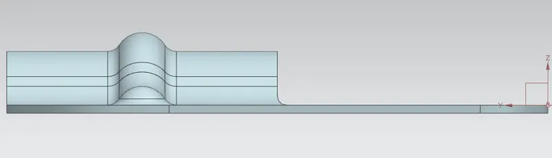
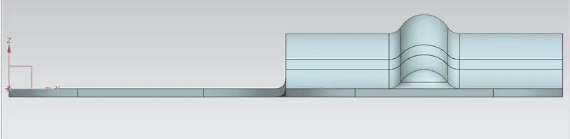
 Various Views of the Bracket Design:
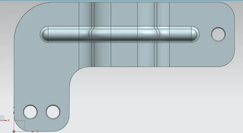
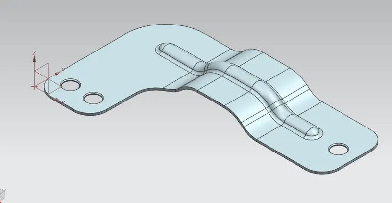 Draft Drawing:
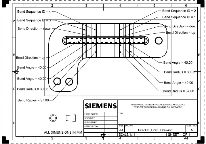
- After the modelling, the manufacturing of the component a technical 2D drawing of the component with accurate dimensions or scales is denoted.
- The draft is created with a scale of 1:1 and using A4 size. and add a new Base View.
- In the Base View dialogue box, select the option Model View to use FLAT-PATTERN#1.
- Set the scale ratio is 1:2
Final Conclusion:
- This odd-shaped enclosure design has been completed by using the sheet metal application in Siemens NX CAD.
- Then the required drawing sheet was created by using the draft application in the NX-CAD.
- NX-CAD is used to maintain our desired design part and to follow the features are applied as per industry workflow.