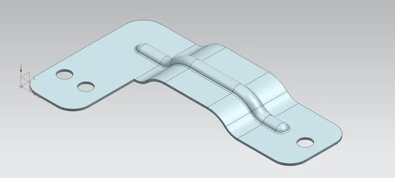
Advanced Sheet Metal Design Using NX Cad Challenge_6_Bracket
Title: Advanced sheet metal design using SIEMENS NX CAD -Bracket
OBJECTIVE: To design a Bracket in Siemens NX Cad with the sheet metal commands.
INTRODUCTION:
SHEET METAL:
Sheet metal is a metal formed by various processes into thin,flat pieces.A metal sheet whose thickness is 6mm is called sheet metal and various processes are carried out on these sheet metal like Blanking,punching or piercing,coining etc.
Usually sheet metal are available in the form of flat sheet plates these flat sheets will undergo different processes based upon the requirement.
NX CAD:
Here in this course we are using SIEMENS NX by which we are going to model some sheet metal parts.
NX CAD has its own advantage over many other CAD softwares in the market,because it is capable of converting the non parametric body into parametric body,can produce sheet metal part from the solid body.
COMMANDS USED:
1.Contour Flange:
It used to create a base feature from a sketch extruding along a axis and giving thickness.
2.Break corner
The break corner is used to give fillet or chamfers at the sharp ends of sheet metal
3.Unbend
The sheet metal can be made flat by giving the fixed face and specifying the bends.
4.Rebend
The rebend works opposite to the Unbend which is used to bring the original shape of sheet metal.
5.Datum plane
It creates a plane along an xy,yz,zx at an offset distance.
6.Bead.
It lifts the part of the sheet metal with a given sketch.
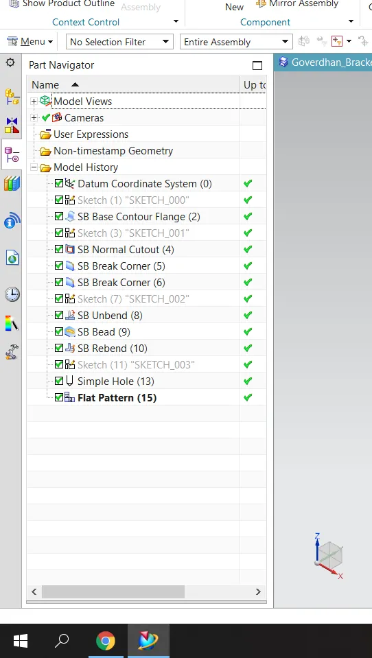
DESIGN METHODOLOGY:
|
CREATING SKECTCH ON XY PLANE. |
↓
|
CREATING A BASE FEATURE ALONG A AXIS. |
↓
|
UNBEND |
↓
|
CREATING BEAD. |
↓
|
REBEND |
↓
|
CREATING HOLE. |
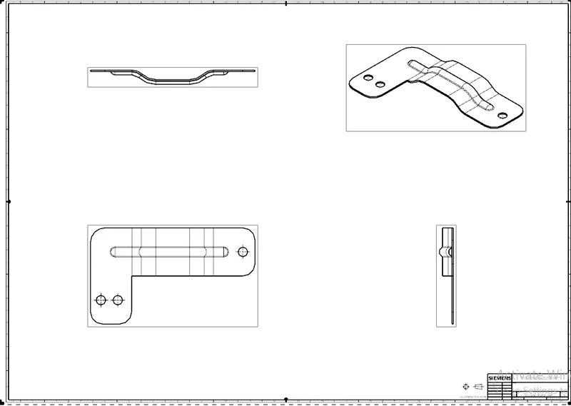
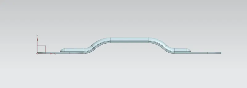
FRONT VIEW:
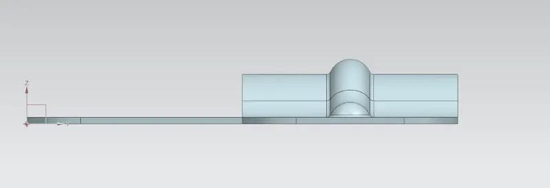
SIDE VIEW:
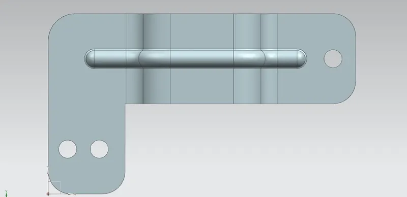
TOP VIEW:
ISOMETRIC VIEW: