Advanced Sheet Metal Design Using NX Cad Challenge_6_Bracket
SHEET METAL BRACKET DESIGN :
OBJECTIVE :
To apply the Sheet Metal design process and to design a Sheet Metal bracket in parametric CAD software Siemens NX following industrial workflow.
INTRODUCTION:
Sheet Metal is a metal with a small thickness ranging from 0.5-6mm which is made thin and flat by rolling or hammering process. A number of mechanical components are made up of Sheet Metal. Sheet metal is widely used in the manufacturing industry due to its various advantages. In this project, a bracket is designed in Siemens NX CAD software following the industrial approach. The use of a parametric modelling environment is the main use made in this project. This project focuses on the stiffening process of a bracket.
DESIGN METHODOLOGY:
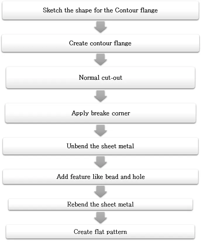
The bracket designed for this project consists of features like contour flange, holes, and beads. Every feature is designed in an order following the industrial procedure to keep the design intent. The design methodology used for this project can be summarized as depicted in the flowchart below :
DESCRIPTION :
SKETCH FOR CONTOUR FLANGE :
A contour flange can be created from any open curve. For this bracket, the sketch is created in an XZ plane with the following dimensions.
CONTOUR FLANGE :
The contour flange is a flange created using the open sketch created in a plane. It is different from regular flange because it can be created in any shape and it doesnot require choosing the edge of any tab or existing flange. It can be at any position or at any angle. For this bracket design, a contour flange is created using the earlier sketch as the curve.
NORMAL CUTOUT :
A sketch is created on the XY plane to cut away the unnecessary material. Then the operation normal cut out is carried out. It cuts away the material at the right
angle with respect to the sketch plane.
BREAK CORNER :
Break corner feature allows you to round off the sharp corners and remove the pointed corners. This is like a fillet feature in other CAD software. It is used to eliminate possible accidents due to sharp ends or to eliminate possible failures and crack propagation.
SKETCH FOR BEAD CREATION :
For this bracket, a straight line is sketched first before applying the unbend feature. A straight line on the XY plane is drawn for this purpose.
UNBEND :
This is a very powerful and very useful tool in Siemens NX. It allows all the bends made by the various features to the unbent state at once. In order to achieve a flat configuration of the sheet metal as per the design intent, it is necessary to choose the bends in order. It is also possible to box select all the bends at once. Once the unbend feature is used, further features can be carried out using the sketches created in the unbent state.
BEAD CREATION :
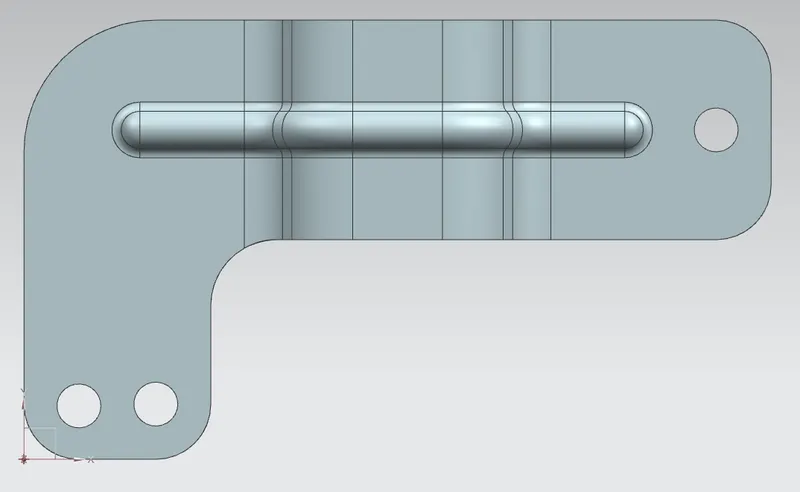
Beads are the features added in sheet metal components in order to increase the stiffness of the component. Beads require a sketch in order to apply the feature. It can be either an open or closed profile. For this bracket, the bead is created selecting the line drawn in the earlier step with a radius of 7 mm.
HOLES :
The hole feature in sheet metal is similar in solid modelling. Here, three general holes of a 20 mm radius are created while in the unbent state.
REBEND :
All the features added after the unbend feature are added in the unbend state itself. After the addition of sketches and additional features are completed, the sheet metal component has to be rebent to the required position. This is done using the rebend feature and selecting all the bends in order or by box selection.
LOCAL RADIUS ANALYSIS :
In NX, the radius value of the parts and models can be easily measured or analyzed by using the local radius tool under the tab ‘Analysis’. Here, the local radius of the bead and the bend radius is measured and shown.
MEASURE DISTANCE :
This tool allows measuring distance between any two references in the part within NX. In this bracket, the distance between the two holes is measured and shown.
DRAFTING :
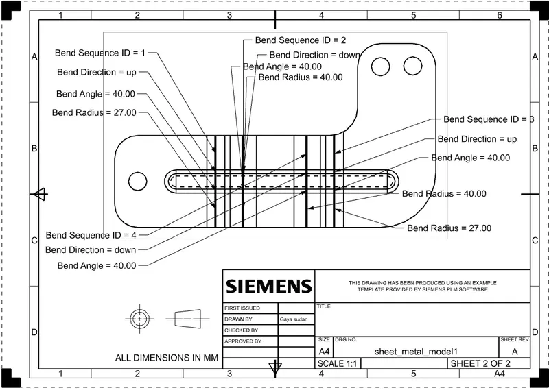
After the design is complete, the execution or the manufacturing of the component requires a technical drawing of the component with the provided scale and with accuracy. The necessary details such as annotations, callouts, bend tables can be added as per the requirement. For this bracket design project, a drawing is created out of the flat pattern in a 1:2 scale in an A4 sheet, and an additional drawing showing different views is also shown.
DIFFERENT VIEWS :
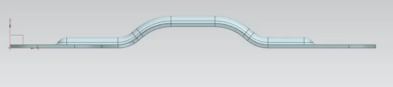
FRONT VIEW :
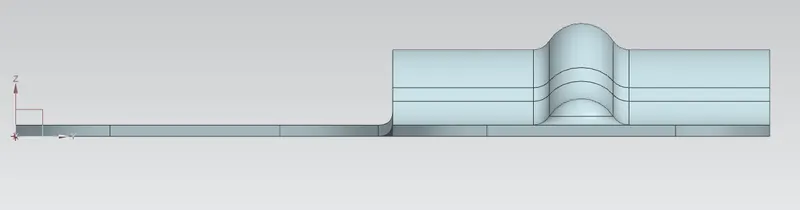
SIDE VIEW :
TOP VIEW :
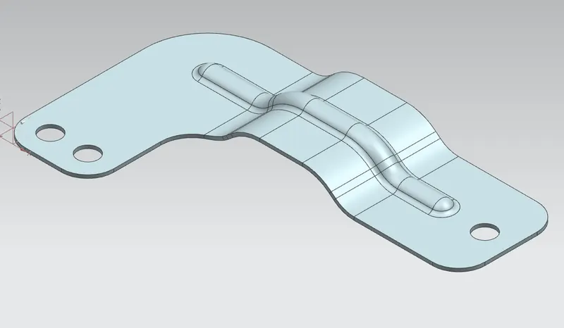
ISOMETRIC VIEW :
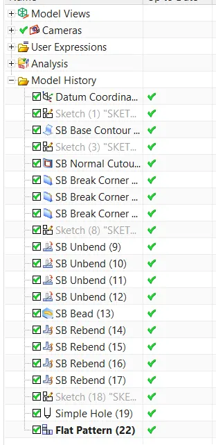
FEATURE TREE :
CONCLUSION :
Thus the modeling of the sheet metal BRACKET has been succussfully completed and the bacis features like contour flanges, normal cut out, break corner, bead, holes, local radius analysis are learnt and applied in the design using SIEMENS NX_CAD.