Advanced Sheet Metal Design Using NX Cad Challenge_6_Bracket
BRACKET
OBJECTIVE:- To create a Bracket using a different sheet metal commands that will help to know about every single command in detail.
INTRODUCTION:- In this project we will learn about the step by step procedure to create Bracket from the given 2d Drawing.
DESIGN METHODOLOGY :-
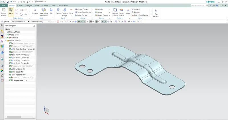
This is the approch that show in the part navigater which command did we do first and then which one
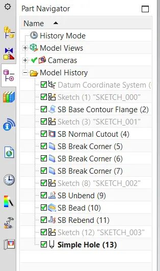
Part Navigater
DESCRIPTION:-
To make the sheet metal Bracket these commands are used :-
Contour Flange:- This command is used to create a base feature by extruding a sketch along a vectore or add material by sweeping a sketch along an edge or chain of edge.
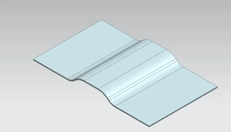
Contour Flange
Normal cutout:- This command we use to cut the sheet metal parts.
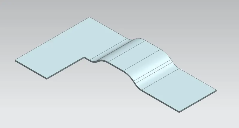
Normal cutout
Break Corners:- This command is used for cutting the sharp corners or edges because on the sharp corners at the stress level is high that's why the sharp corners brake eassily to prevenrt the corners we used break command .
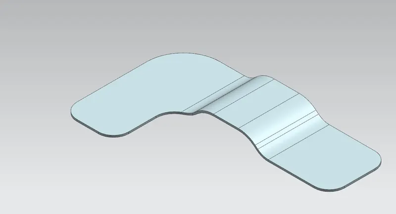
Break Corners
Unbend:- This command used for to unfold the part.
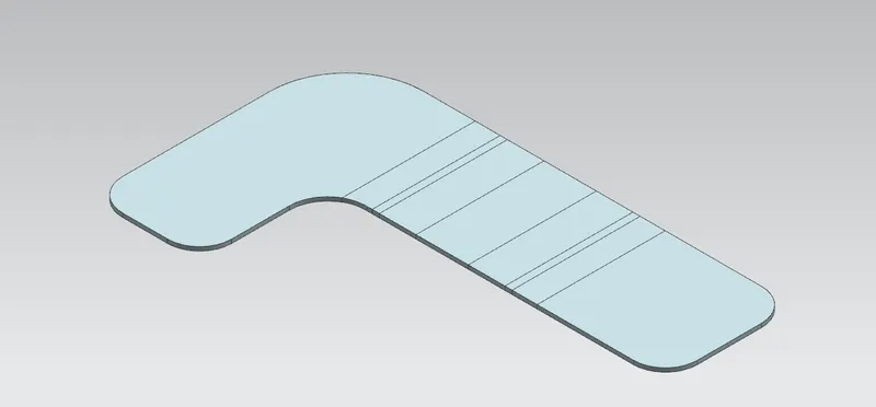
Unbend
Bead:- This command is used for lift the material along the contour of a sketch that is simillar to the dimple command.
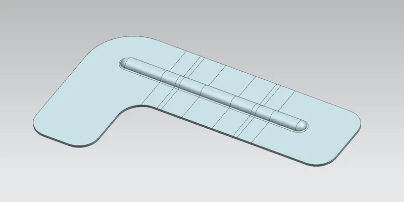
Bead
Rebend:- This is used to unfolded part to make folded part.
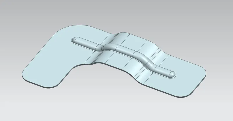
Rebend
Hole:- This command is use to make the diffront types holes.
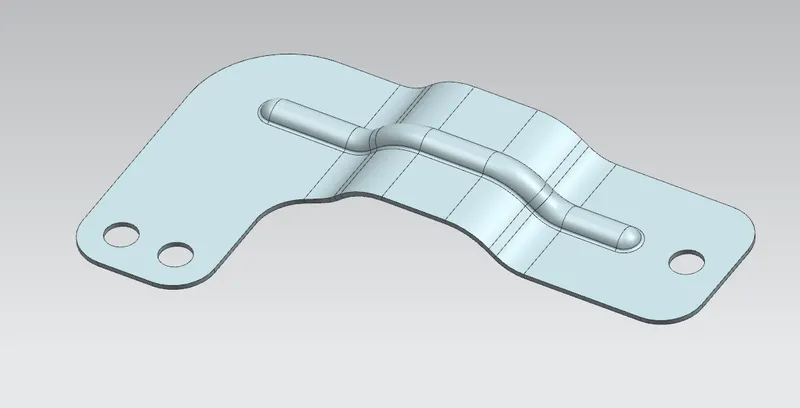
Hole
MODEL REPORT:-
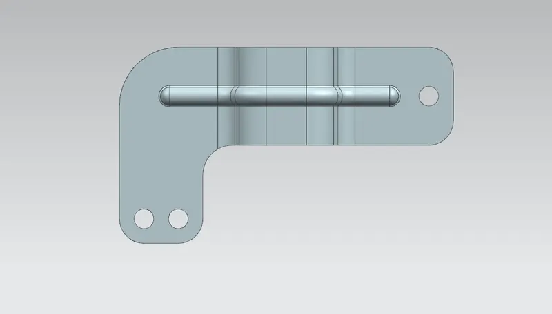
Top View
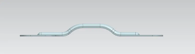
Front View
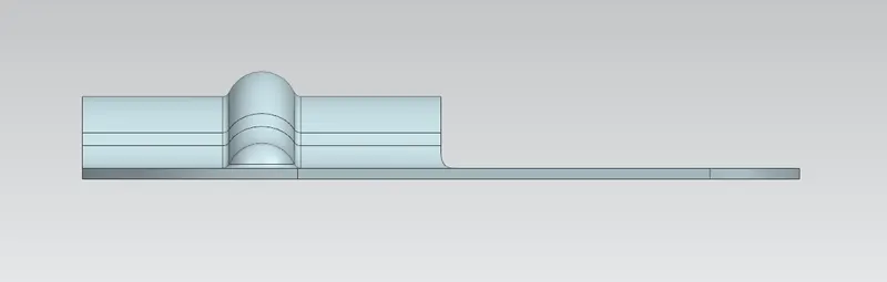
Side View
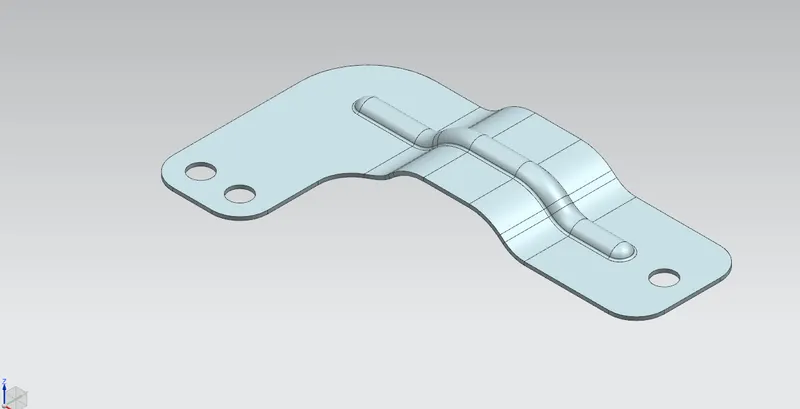
Isometric View
DETAILED DRAWING:-
CONCLUSION:- In this project we learn the step by step procedure to create Bracket from the given 2d Drawing.