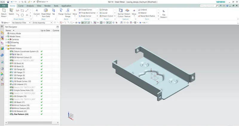
Advanced Sheet Metal Design Using NX Cad Challenge_1_Casing Design
Casing Design
OBJECTIVE:-
How do we use the command in sheet metal and if any probleme comes while doing the use of commands,how can we solve them .
INTRODUCTION:-
In this Project we will learn the step by step procedure to design a sheet metal casing by using the NX sheet metal.
DESIGN METHODOLOGY :-
This is the approch that show in the part navigater which command did we do first and then which one
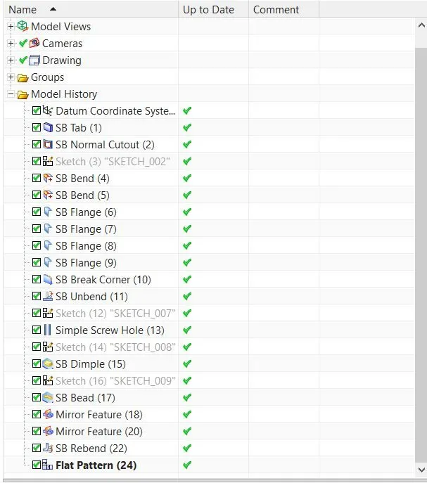
Part Navigater
Description:-
To make the sheet metail casing design these commands we used:-
- Tab:- This command use to make a sheet metal base part.
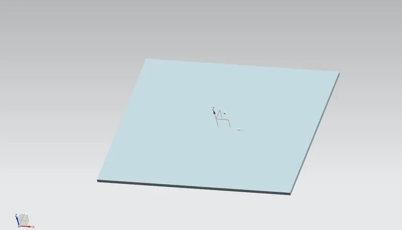
(Tab)
- Normal cutout:- This command we use to cut the sheet metal parts. Normally this command preoffer to cut the sheet metal parts.
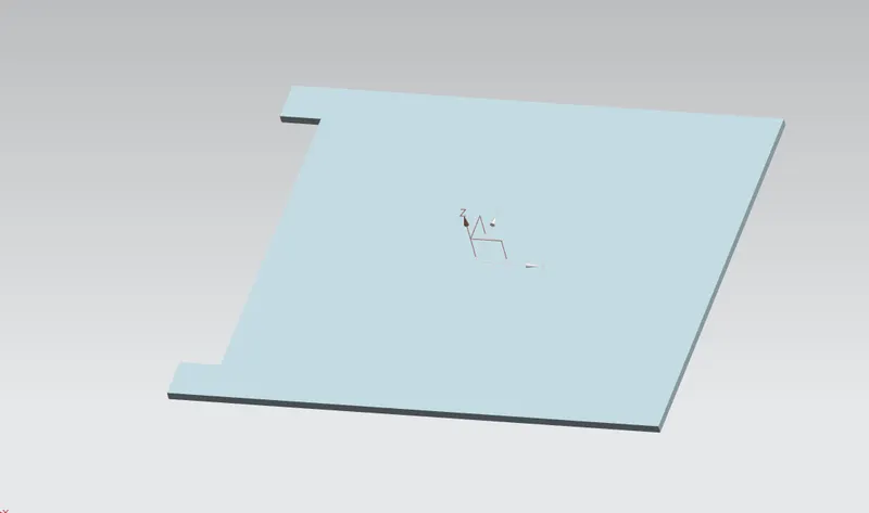
(Normal cutout)
- Bending:- This command genrally used for bending the sheet metal parts.
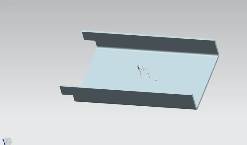
(Bending)
- Flange:- This command used for create a new flange in any direction at any angle.
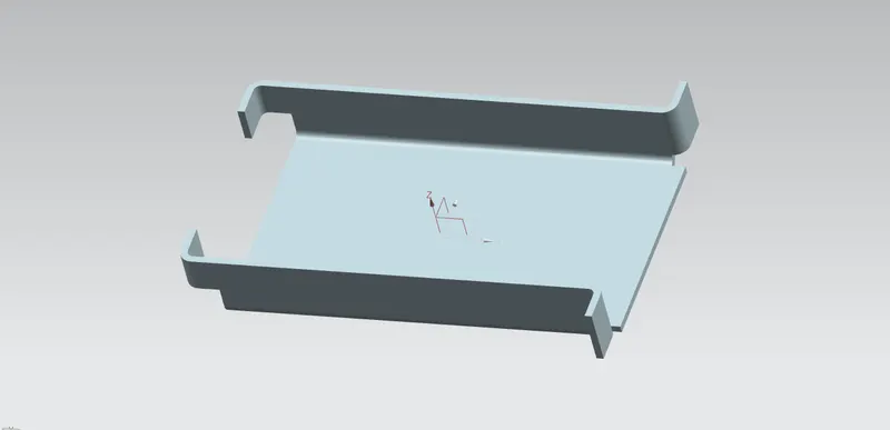
(Flange)
- Break Corners:- This command is used for cutting the sharp corners or edges because on the sharp corners at the stress level is high that's why the sharp corners brake eassily to prevenrt the corners we used break command .
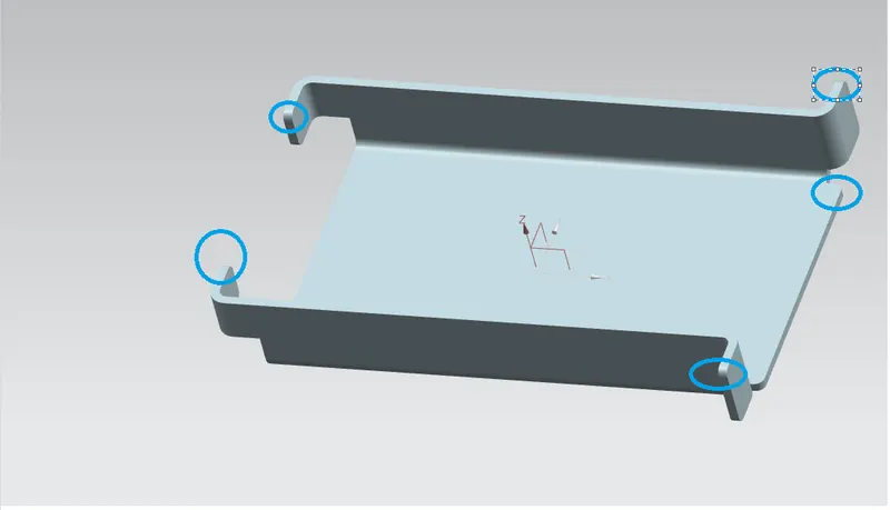
(Break Corners)
- Unbend:- This command used for to unfold the part.
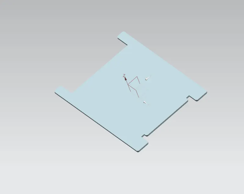
(Unbend)
- Hole:- This command is use to make the diffront types holes.
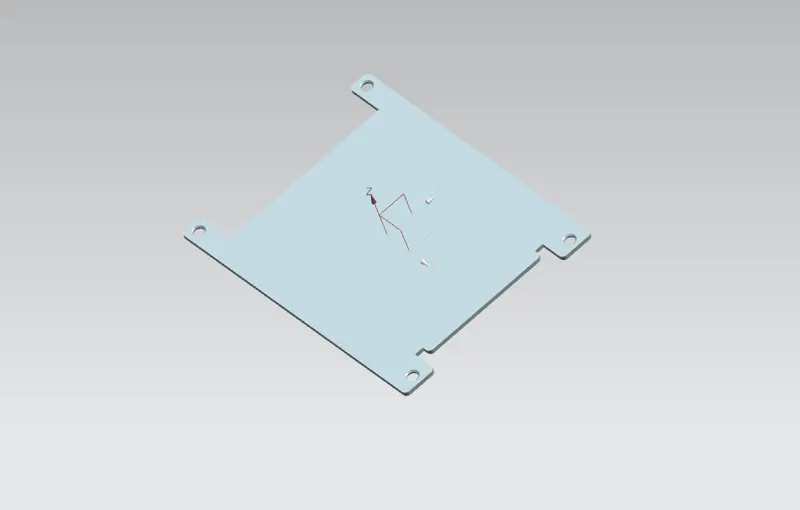
(Hole)
- Dimple:- This command is used to lift the area of a model that inside a sketch.
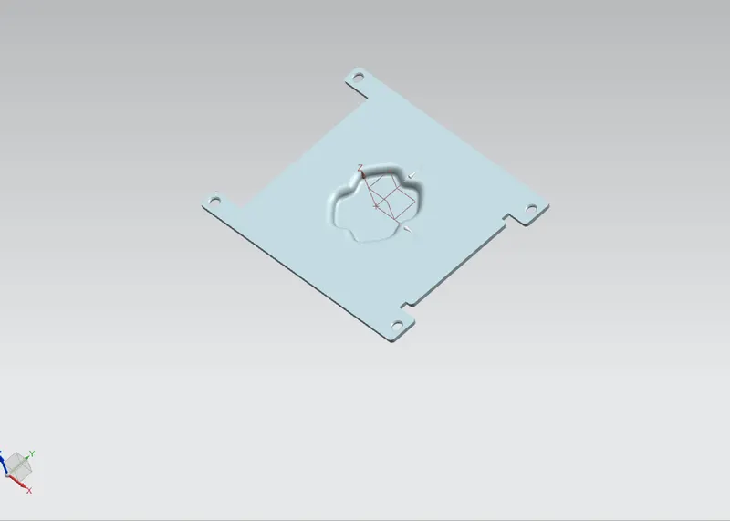
(Dimple)
- Bead:- This command is used for lift the material along the contour of a sketch that is simillar to the dimple command.
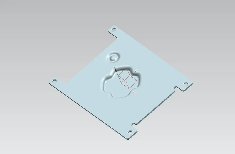
(Bead)
- Mirror Feature:- This is used to mirror the feature.
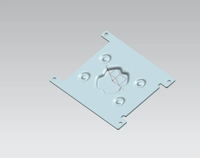
(Mirror Feature)
- Rebend:- This is used to unfolded part to make folded part.
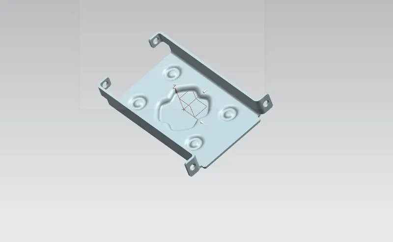
(Rebend)
- Flat Pattern:- This is final process to get the Flat pattern of the sheet metal part.
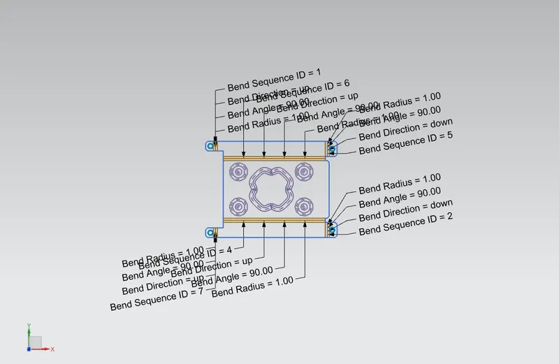
(Flat Pattern)
MODEL REPORT:-
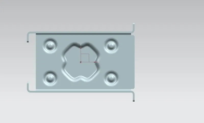
Top view
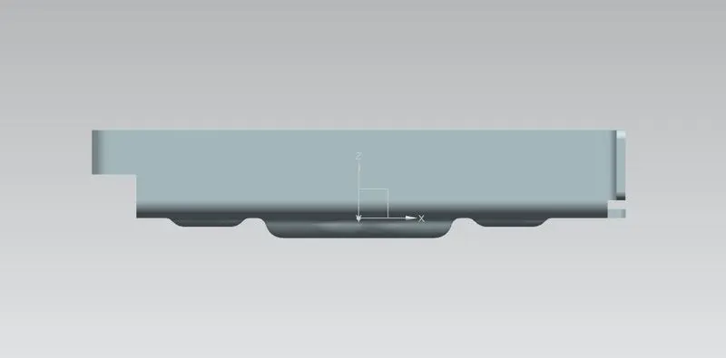
Front view
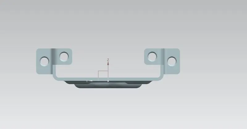
Side view
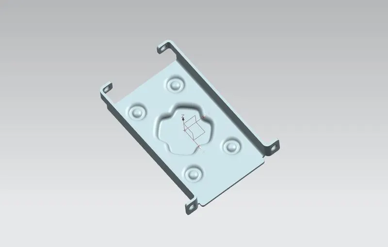
Isometric view
Detailed Drawing:-