Advanced Sheet Metal Design Using NX Cad Challenge_6_Bracket
Title: Sheet metal Bracket
Objective: Design of sheet metal Bracket using Siemens NX CAD.
Introduction: Basic Principles Sheet Metal Fabrication is the process of forming parts from a metal sheet by punching, cutting, stamping, and bending. 3D CAD files are converted into machine code, which controls a machine to precisely cut and form the sheets into the final part. In this project, we design the sheet metal casing design using NX CAD software with given parameters values.
Design methodology:
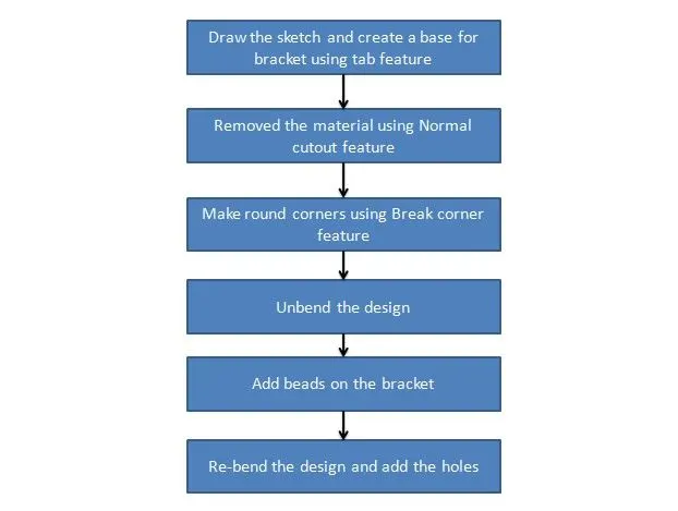
Description:
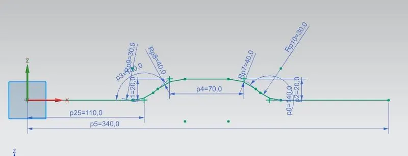
Select the XZ plane and draw the 2D sketch.
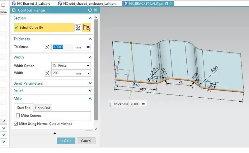
Use Contour Flange on the sketch of 3mm thickness and 200mm width.
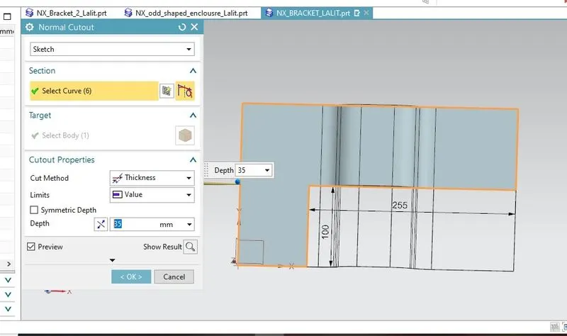
Select the surface and draw a rectangle of 255mm length and 100mm breadth.
Use the Normal Cutout feature and remove the unnecessary material.
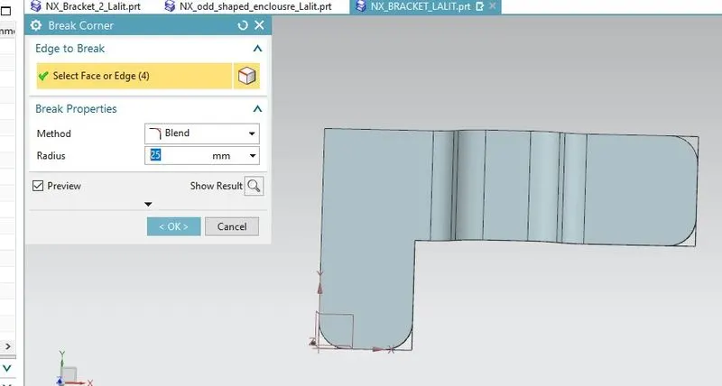
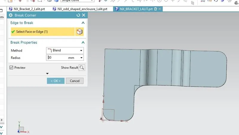
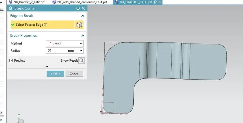
Use break corner feature to make round corner of 25mm,30mm, and 60mm radius.
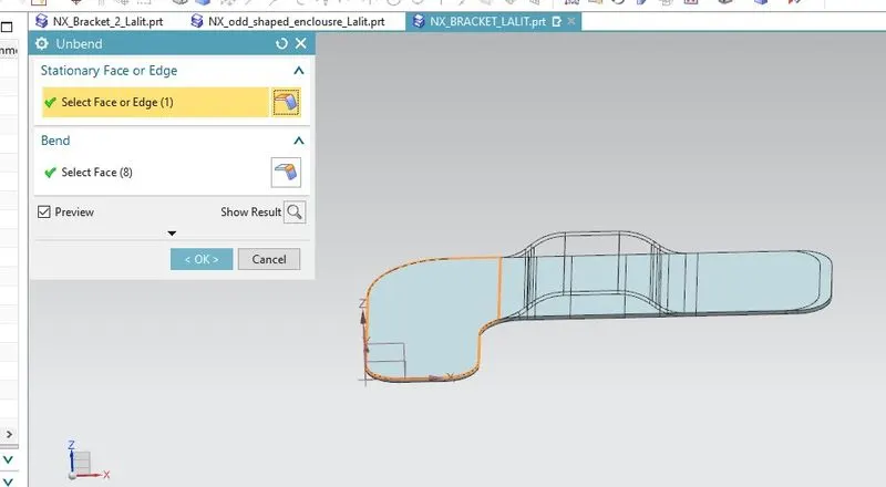
Use unbend feature and unbend the backet.
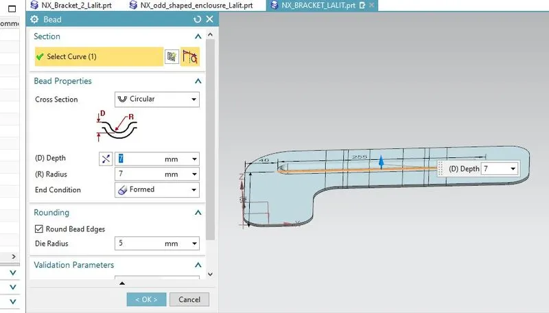
Use the Bend feature and create a bend of 7mm depth.
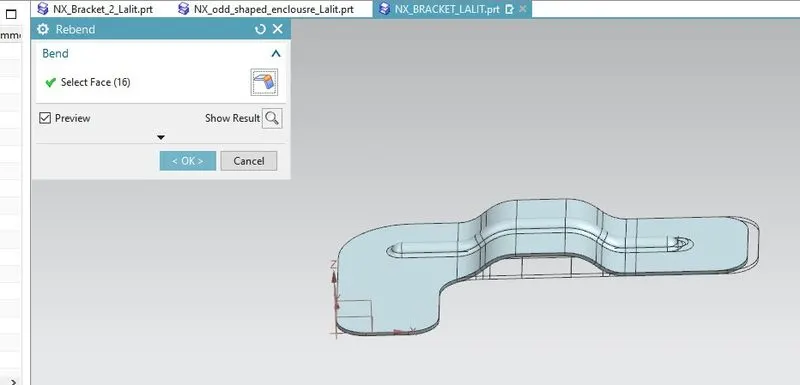
Rebend the sheet metal bracket.
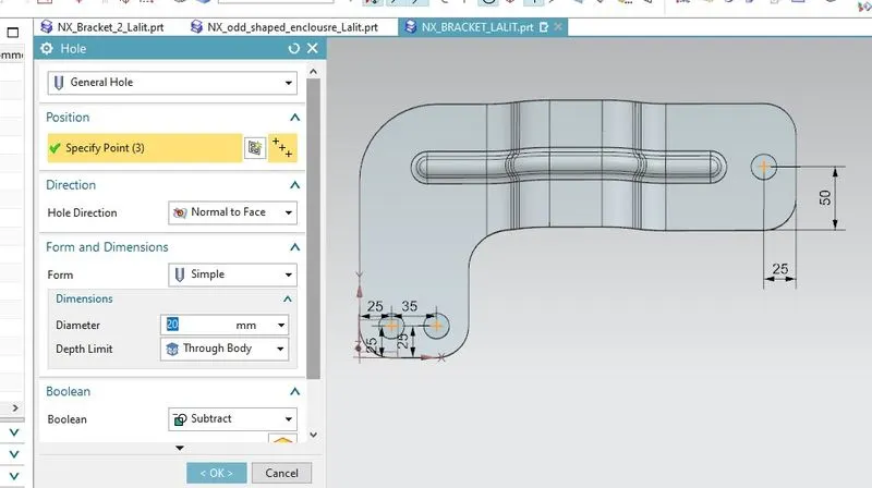
Use the Hole feature and create holes of 20mm diameter.
Views:
Isometric View:
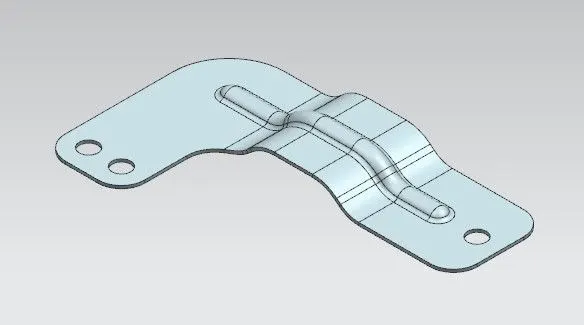
Front view:
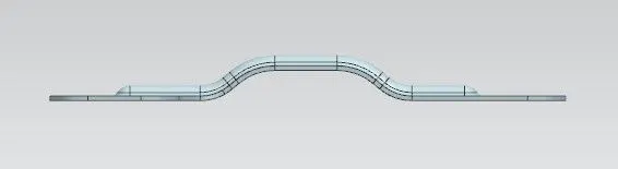
Side view:
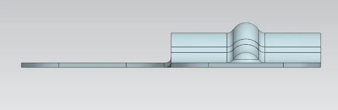
Top view:
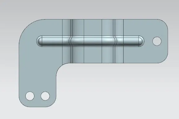
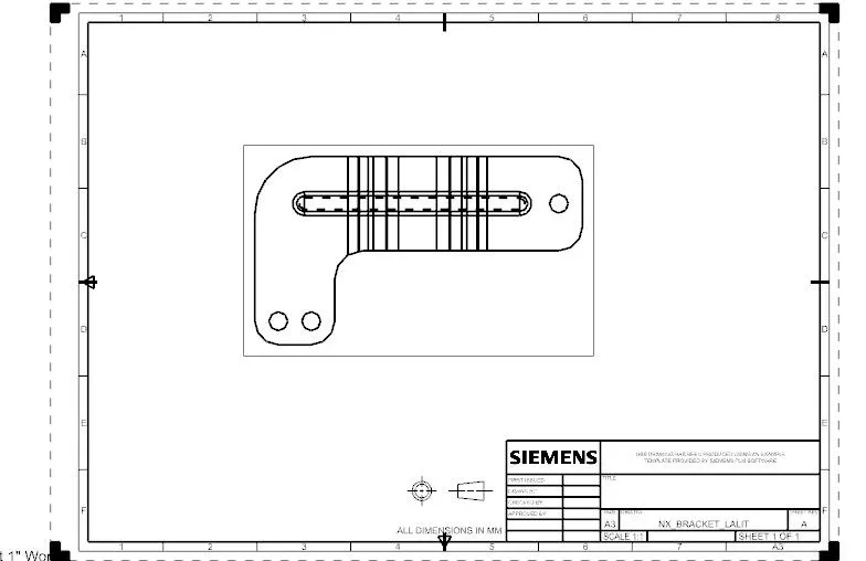
Drawing sheet:
Conclusion:
- Learn about the sheet metal design of casing using NX CAD.
- Learn about the design of some features like flange, dimple, bead, break corner, unbend, rebend.
- Learn about the creating of a 2D drawing sheet of the design.
- Learn about the sheet metal standards and fundamentals.