Advanced Sheet Metal Design Using NX Cad Challenge_6_Bracket
Title: Bracket
Objective: Creation of Bracket using NX CADA
Introduction:
A sheet metal bracket is nothing but a projection from a wall or overhanging from the wall to carry weight. Bracket are often in the from of volutes or scrolls and can be carved, cast or molded. These are manufacturing by conducting stamping or die casting opertion. These brackets found their application from mounting of any products starting from antennas to TV, street lights and many more.
Design Methodolgy:
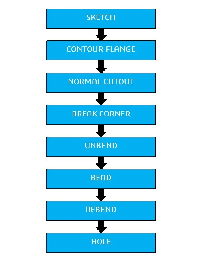
Description:
Tab:
This feature is used to create a solid body by extruding the sketch along a vector by given thickness value or it is also use to add material along a planer face.
Normal Cut-Out:
This feature cuts or removes material from an existing solid body by projecting the sketch along the model and then cuts perpendicular the faces which intersects the projecting sketch.
Bend:
It modifies the model by bending it on one side of drawn sketch line their by providing smooth round profile to the corners.
Contour Flange:
Create a base feature by extruding a sketch along vector or adds material by sweeping a sketch along an edge or chain of edges.
Break Corne
It round or breaks the sharp corner of the tab create there by providing smooth round profile to the corners.
Unbend:
It is used for unbend the corner of the body.
Bead:
It is used to create a conture shape according to the sketch in the required direction with required punch/die radius.
Hole:
A hole feature is used to create holes in the body.
Rebend:
It is used for bending corners of ther unbend body.
Flat pattern:
Flat pattern is used to create flat pattern view which is used for drafting purposes.
Procedure for designing the bracket:
First of all create a sketch for sheet metal bracket on the front plane ( XZ plane).
- To create sheet metal surface using Counter flange feature.
- Then the normal cut out opertion has execute by draw the require sketch and then remove the unwanted portion.
- Give fillets to conners to get smooth corners as per design parameters.
- Then add some features like bead the bracket is unbent using un-bend command.
- After un-bending the bracket the required bead is applied for stiffingthe bracket.
- Now the bend operation is rebend by using Re-bend feature.
- Before creating the hole the local radius of the bead must be analyze.
- Finally the bracket is designed completly by adding three holes as required.
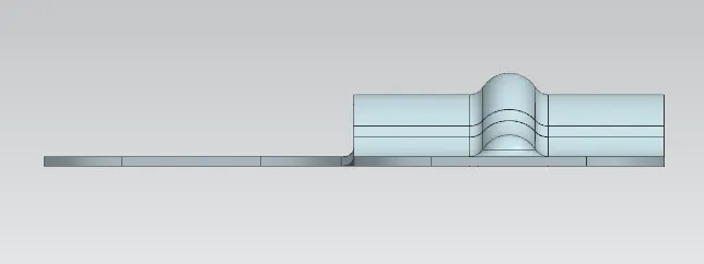
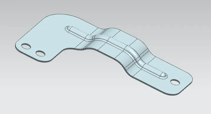
Different view of the Bracket.
Front View
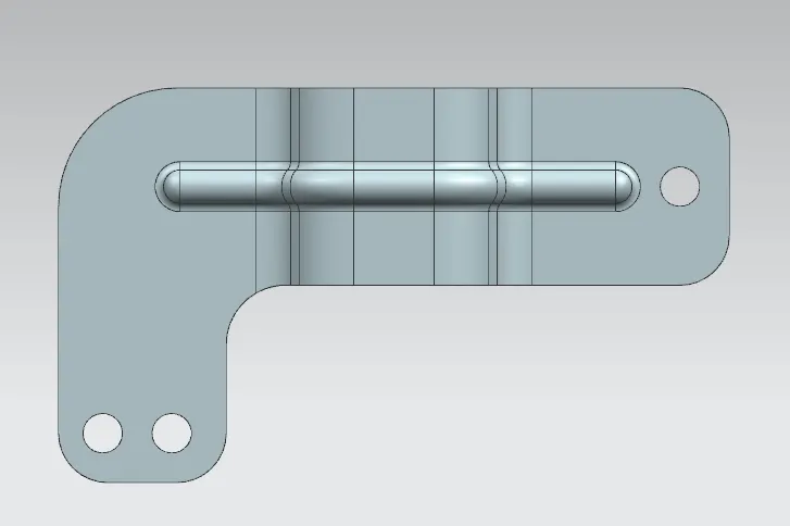
Top View
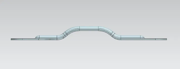
Bottom View
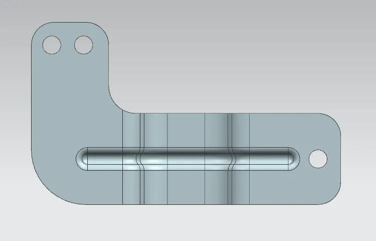
Right Side View
Isometric View
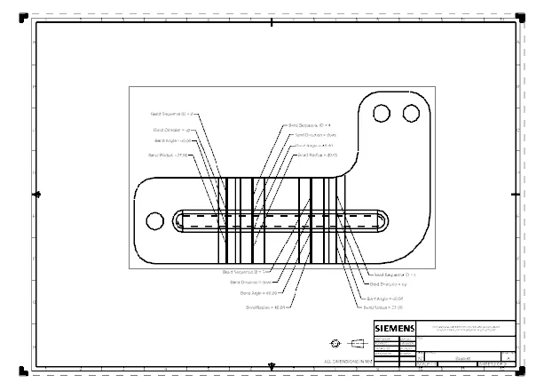
Drawing Sheet
 Conclusion:
Thus the design has been completed as per design parametres using Sheet metal application in Siemens NX and also required drafting has been done using drafting features in NX cad.