Advanced Sheet Metal Design Using NX Cad Challenge_6_Bracket
DESIGN OF SHEET METAL BRACKET USING NX CAD
OBJECTIVE:
To design the bracket in advanced sheet metal by using NX cad software and learn the tools and features used.
INTRODUCTION:
The sheet metal can be formed and created into differnt shapes and sizes as per requirement. This process is simple and less costlier to be used in manufacturing industries.
DESIGN METHODOLOGY/ APPROACH:
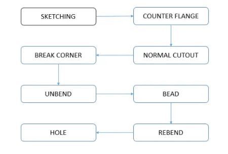
DESCRIPTION:
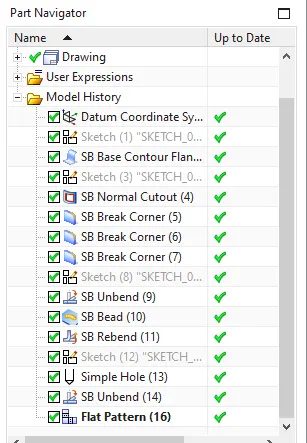
- SKETCHING
To draw the base of sketch for modelling.
- COUNTER FLANGE
It is used to extend the sketch to respective axis with thickness as required from base.
- BREAK CORNER
It is used to create round shaped finished edges .
- NORMAL CUTOUT
It is used to create cut portions as per requirement on the base.
- UNBEND
It is used to flatten bent metal into flat sheet.
- BEAD
It is used to create contour shape as per requirement.
- HOLE
It is used to create hole with differnt options on the sketch.
- REBEND
It is used to rebend the flat sheet to orginal bent metal.
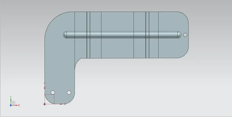
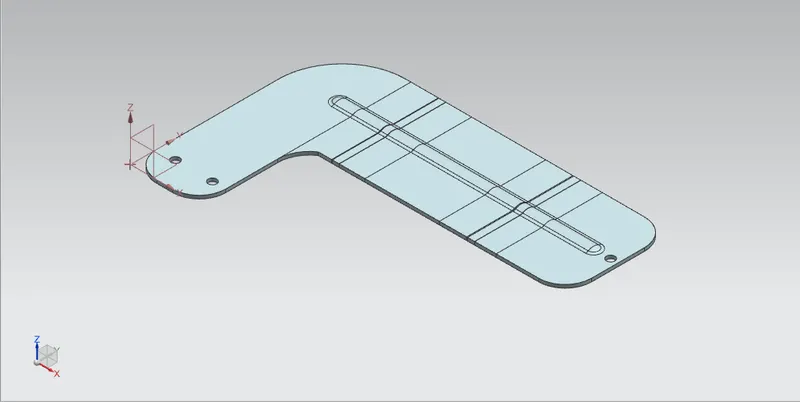
SCREENSHOTS OF BRACKET IN DIFFERENT VIEWS:
front view
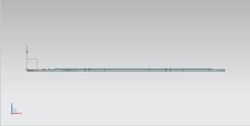
left view
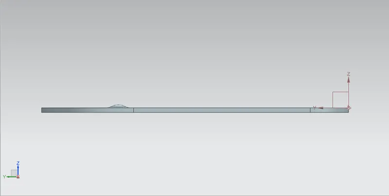
bottom view
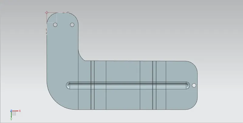
top view
isometric view
feature tree
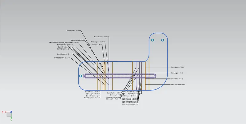
FLAT PATTERN IMAGE:
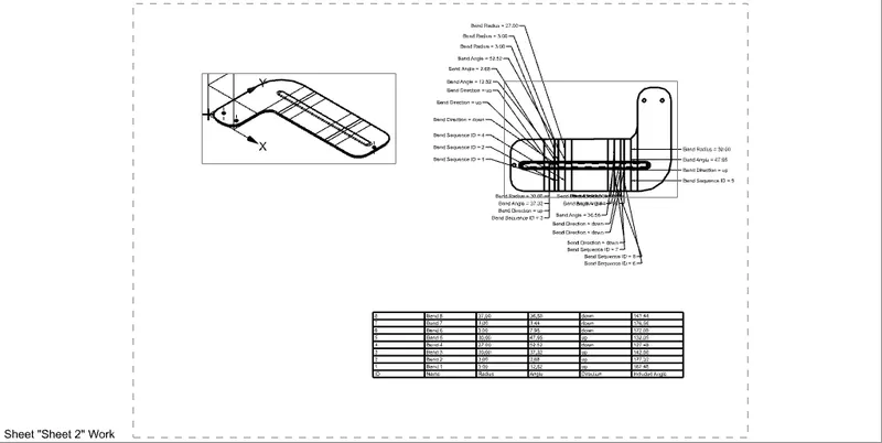
DRAWING SHEET IMAGE:
CONCLUSION:
Thus in advanced sheet metal for designing bracket using NXcad software is done.