Advanced Sheet Metal Design Using NX Cad Challenge_5_Odd Shaped Enclosure
PROJECT: Advanced sheet metal design using Siemens NX CAD - Odd-Shaped Enclosure.
OBJECTIVE: To design an Odd-Shaped Enclosure and create a draft of it using the Siemens NX Sheet metal application.
INTRODUCTION: Sheet metal is formed by an industrial process into thin, flat pieces. Sheet metal is one of the fundamental forms used in metalworking, and it can be cut and bent into various shapes. Countless everyday objects are fabricated from sheet metal. Thicknesses can vary significantly; extremely thin sheets are considered foil or leaf, and pieces thicker than 6 mm (0.25 in) are considered plate steel.
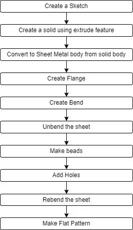
DESIGN METHODOLOGY: The design methodology is explained by the flow chart as follows:
DESCRIPTION:
Sketch: It is the basic of any design.
Flange: It is used to create an extended part (bend) of a sheet metal. There are a total of twelve flanges created in the box assembly.
Unbend: This feature is used to unbend the adjacent bends and flatten them. Here it is used to create cutouts for the hinges.
Rebend: It is used to rebend the corners that were bent before along with any features added after the unbend feature.
Bead: It lifts material along the contour of a sketch that simulates a stamping tool, it is used to give strength to the sheet metal. There are a total of four beads created around the dimple at the base.
Extrude: It creates a feature by extruding a section along a vector.
Sheet Metal from solid: It builds a sheet metal model that takes its shapes from a collection of planar faces. This command is used to convert the solid body into a sheet metal body. After selecting the command and the solid body, we can also remove the edge sharpness by removing the material at these places.
Hole: It adds a hole to one or more solid bodies in a part or an assembly with options for counterbored, countersunk, and threaded. Here six simple holes are created on the unbent surface with a diameter of 10mm. It can be used to make customized or standardized holes along with a defined point or path. The depth of the hole can be controlled.
Flat pattern: It creates a flat pattern feature from the formed sheet metal part. The user chooses this command to create a flat view of the sheet metal after unbending all the sides and faces. This view can be used in drawing the flat pattern along with the bend radius and other dimensions.
IMAGES:
Front View:
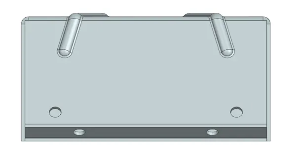
Back View:
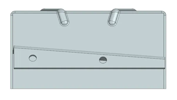
Top View:
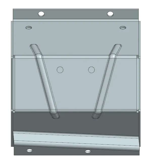
Bottom View:
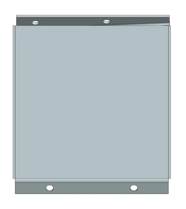
Side View:
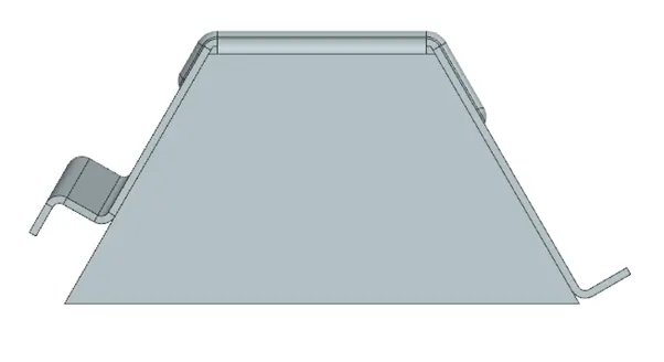
Isometric View:
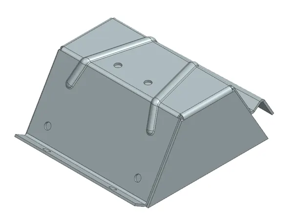
Conclusions: The Sheet metal design of an odd-shaped enclosure was completed using the basic commands such as Tab, Flange, Sheet Metal from solid, Bend, Hole, Unbend, Bead, Flat pattern. These basic commands have influenced the designer to maintain geometric constraints and achieve the final product.