Advanced Sheet Metal Design Using NX Cad Challenge_5_Odd Shaped Enclosure
AIM-AUTOMOTIVE SHEET METAL DESIGN OF ODD SHAPED ENCLOSURES.
OBJECTIVE-Design of odd shaped enclosures with the sheet metal with solid command.
INTRODUCTION
Sheet metal is mostly used in automotive industries for the manufacturing of automotive parts because it is a fast & easy process with less cost. sheet metal is a comprehensive cold working process for metal sheets.
To convert the solid body into sheet in nx cad there are specified tools which helps to design easily as per our required model standards.
SHEET METAL WITH SOLID COMMAND-This operational command helps in converting the solid body to the sheet metal so that we can add some more required features.
DESIGN METHODOLOGY
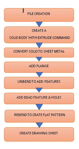
TOOLS USED TO DESIGN
EXTRUDE- A solid body can be created using this command by selecting a sketch as a curve at required length alonh vector.
FLANGE- by selecting the edges of the sheet metal a bend is created by adding the filled as default as we required by given the dimensions as input to it.
JOF- This command is to used to bend the sheet into l shape by selecting a single curve as input by giving the length & bend radius it creates a bend portion upon our requirements.
BEAD- To add bead feature on the sheet metal firstly need to create a sketch on pirtucal face where we need the bead to apply actually the need of bead is to add smoe strength to the flat sheet metal part.
HOLES- create a scetch on the required face & select the circles as cures & chnage the vector direction & give radius of the metal to be trimmed.
UNBEND- this feature is used to make the completed complex shaped model nto a flat sheet to selecting a stastionary face & select complete model.thus the required model is obtained.
REBEND-this feature is used to make the unbend model to regin its original shape after adding the additiona;l feature on it by select a single drag .
PROCEDURE
- open a new file of sheet metal & rename it as sheet metal from solid.ok
- create a sketch on the xz plane & draw the line as a closed path as per required dimensions as 200 mm HOR line,ang 60deg,both side & join the two points & create the closed sketch ok
- select the extrude command & select the drawn sketch as curve & give vector as length 200mm ok.
- select the sheet metal with solid command & select the top face & two adjacenet faces ok.& select the other face required to make sheet metal & select the edges as bend edges as the same for other side.
- create a flange at bottom side by selecting the edge of 20mm length & 90deg as angle.ok
- Adding the bends of the flat face on the other side create the side on the face & draw a line inclined exit.
- select the jog command & select the curve as drawn sketch & give 20 mm height & change the material inside as referance ok.
- unbend the designed model by selecting the upper face as stastionary face & drag select complete model pk
- creating of bead on the flat sheet metal
- create a sketch on the face required to add beads
- select the bead command & select curve drawn & give dimensions.
- Add holes by creating the sketch on the face & give the direction & dimensions required to be trimed.
- Rebend the unbend sheet metal after adding the required features on the model to regain its original shape.
- create flat pattern by selecting the to face & give orientation method edge.ok
- create a drawing sheet with apporpriate size of sheet & ration & add base views in it.
ODD SHAPED ENCLOSURE VIEWS
ISOMETRIC VIEW
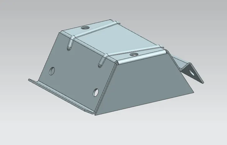
TOP VIEW
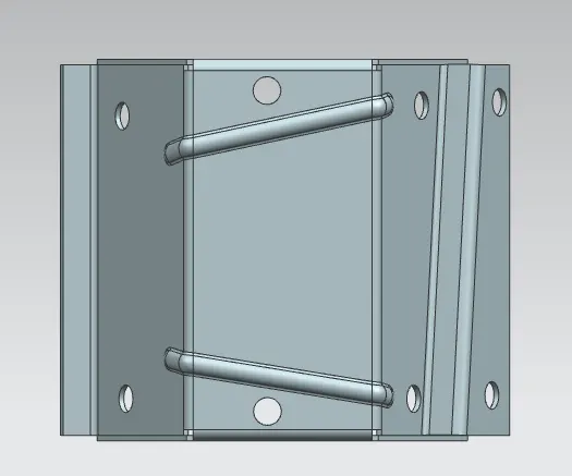
SIDE VIEW
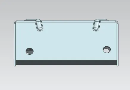
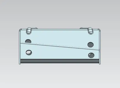
BOTTOM VIEW
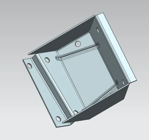
FLAT PATTERN VIEW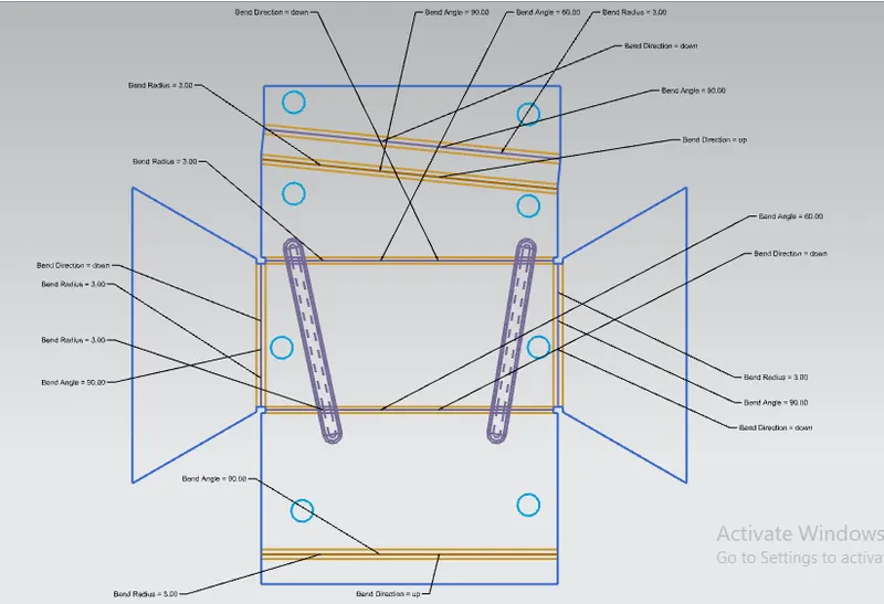
DRAWING SHEET (drafting)
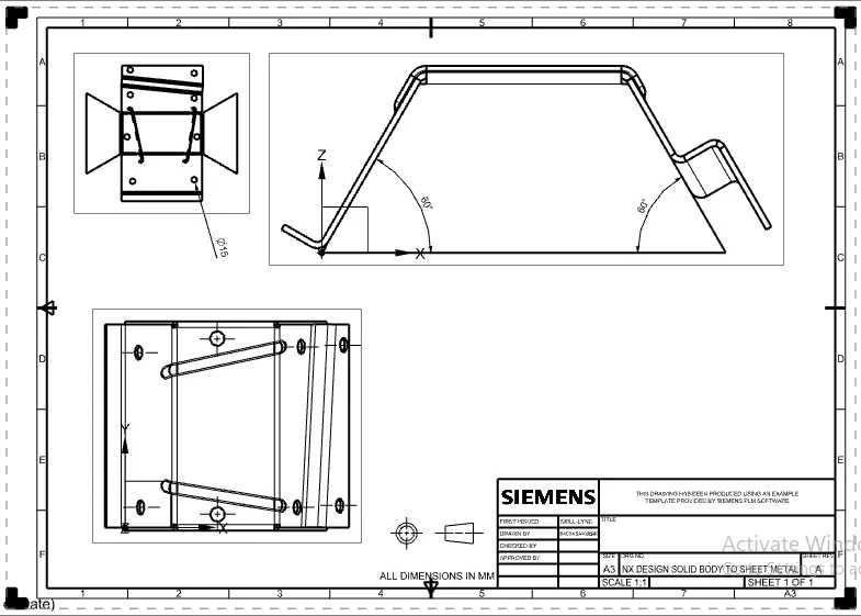
CONCLUSION-DESIGN OF THE SHEET METAL WITH SOLID & DRAFTING IS DONE AS PER THE REQUIREMENTS.& RELAVENT IMAGES & FILES ARE ATTACHED IN THE ANSWERBOX.CONVERTION OF SOLID TO SHEET METAL AS BEEN LEARNT IN THIS CHALLANGE.