Advanced Sheet Metal Design Using NX Cad Challenge_5_Odd Shaped Enclosure
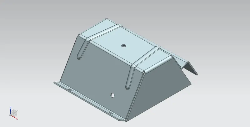
Title of the Project – Advanced Sheet Metal Design Using NX Cad - Odd Shaped Enclosure.
Objective – To show the recommended workflow procedure to design a Sheet Metal part of Odd Shapes.
Introduction – NX sheet metal design incorporates material and process information in sheet metal-specific modelling features: bends, flanges, tabs, cut-outs, beads, dimples, louvers, corner and edge treatments, patterns and other formable features.
Design Methodology –
Flow Chart -
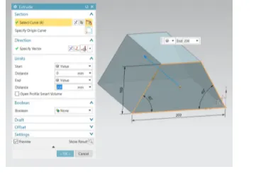
- Create solid body that enclose the interior volume of the final enclosure shape, extruding the sketch drawn 200mm along negative z direction.
- Wrapping the solid body with sheet metal by using feature sheet metal from solid by selecting appropriate web face and bends on bends on solid body.
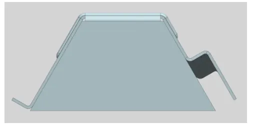
- Selecting the LHS part of the sheet metal in isometric view apply a flange of length 20mm and 90 degree.
- Applying joggle feature on the RHS part of shett metal of a sketch shape approx angular type and height 20 mm.
- Entire sheet metal body is unbent selecting near bends.
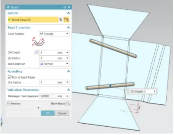
- On the top face of unbend sheet metal bead feature applied depth is 3mm.
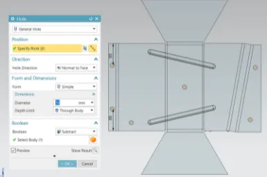
- Hole of 10 mm diameter is appied on the sheet metal center and 2 hole both the sides of unbent sheet metal.
- Re-bend the sheet metal to its original from with bead , flange and joggel feature on it.
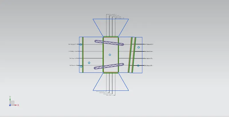
- Create flat pattern selecting the face and direction of the sheet metal.
- Only bend radius,bend angle is made to view in the flat pattern visibility.
Features used –
1. Sketch – It’s the base 2D drawing where it’s drawn on selecting a plane.
2. Tab - It’s base feature part of the sheet metal.
3. Flange -Its extended part of sheet metal obtained by selecting edges.
4. Unbend –This feature unbends the sheet metal part selecting any face as stationary face.
5. Rebend – It brings back the sheet metal to its original shape.
6. Dimple – It’s a kind of die press applied on sheet metal to obtain the required to obtain the desired shape.
7. Bead - This feature gives strength to sheet metal part.
8. Joggle – Creating a step type feature selecting the face of the sheet metal by giving height.
DESCRIPTION :
Extrude:- This feature is used to make a solid body by creating a required sketch.
Flange:- An extended part of the existed component with various width options to be modified with the desired angle, bend radius, relief, length by selecting any edge of the component. 'Flanges' are the external or internal by-products that serve either to increase strength or for attachment with any other object.
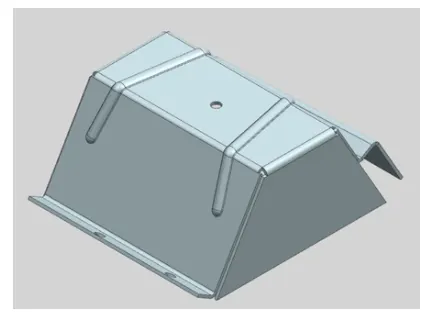
Bead:- 'Bead' can is of different cross-sections like circular, v-shaped & u-shaped along with parameters like depth, radius, die radius, end condition and tool clearance.
HOLE:- 'Hole' is the part of the component either to be removed or to be filled, it can be in any form (general form, drill size hole, screw clearance hole, etc). For creating a hole we just need to define a centre point. Rest features will be controlled by the working tab, hole type, dimension, fit type, depth limit, screw-type etc.
FLAT PATTERN:- 'Flat Pattern' operation is used to create a 2D pattern of the final component with all centrelines, bending curvature lines, flanges line, holes & their centres with detailed specifications.
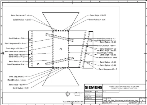
DRAFTING:- This is a general drawing sheet formation with a 2D drawing with proper representation as per scale.
Views -
Front View -
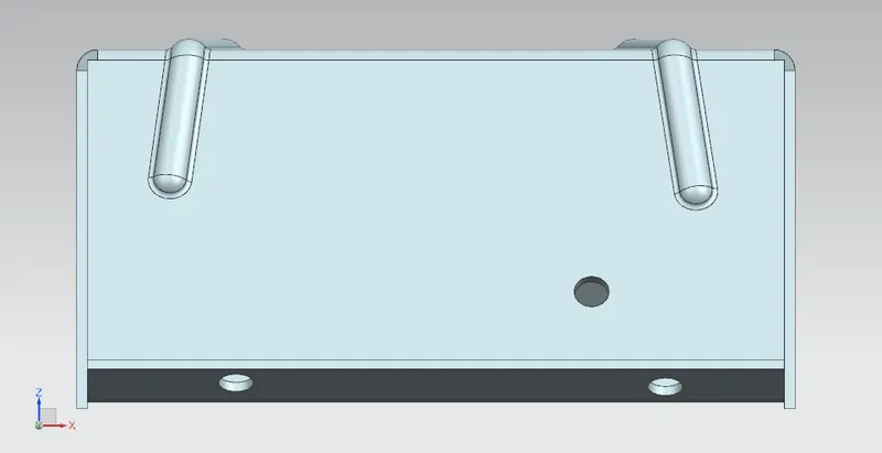
Side view -
Left View -
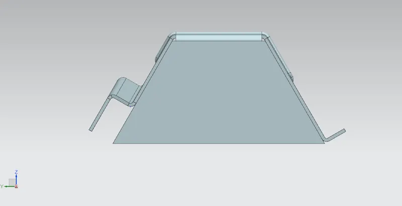
Right View -
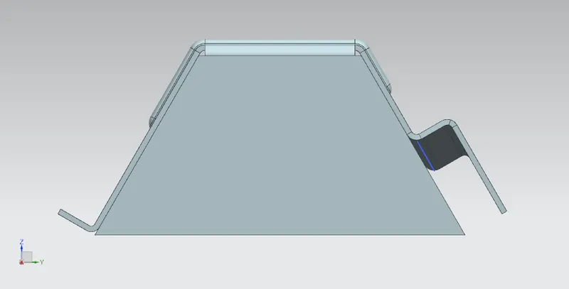
Top View -
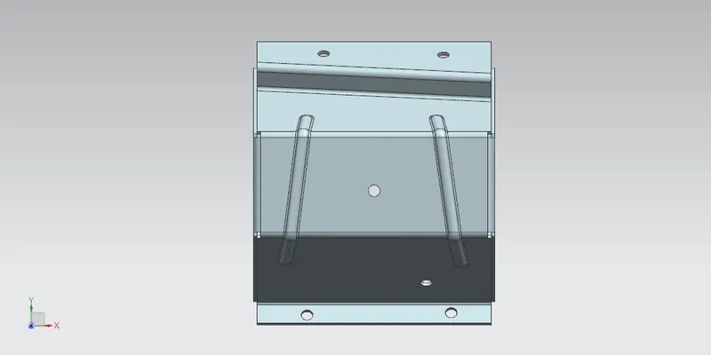
Bottom View -
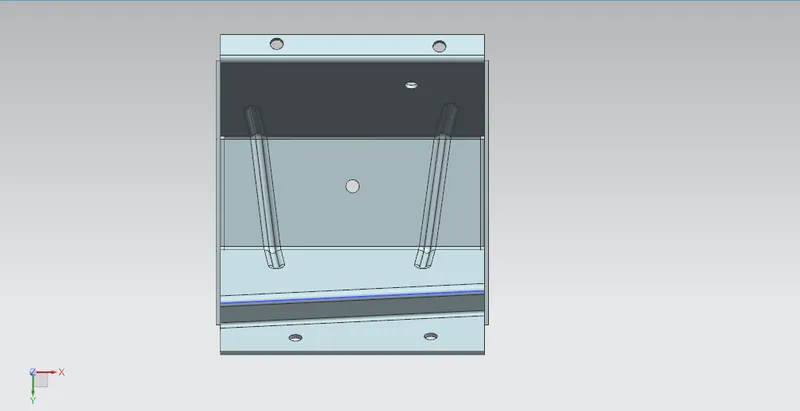
Isometric view -
CONCLUSION:-
In this project, I have learnt "SM Wizard" of 'Sheet Metal' to design different products. All these features include knowledge from Basic to Advanced level of drafting technique. All introductory 'Graphics User Interface' is learnt in this project work before starting any of the main designing parts. Different drafting tools are used here for drafting & modelling. The tools used in this project to create features by "SM Wizard" and tabs, bend, mirror, bead, hole, unbend, rebend, flat pattern, drawing sheet. After this modelling & drafting of 'Odd Enclosure' is completed, an A3 drawing sheet is created with as required parameters for designing.