Advanced Sheet Metal Design Using NX Cad Challenge_5_Odd Shaped Enclosure
SHEET METAL DESIGN OF ODD SHAPED BOX ASSEMBLY USING NX CAD
OBJECTIVE
To design a sheet metal odd shaped box assembly by using siemens NX cad software.
INTRODUCTION
Sheet metal Design is the process of making thin sheet metal into different forms done by the of NX cad software. This helps to know how to use the basic type of sketch tool, Bends, Corners, Punches, Forms, Features in NX Cad.
METHODOLOGY
- Sketch
- Extrude
- Sheet metal from solid
- Flange
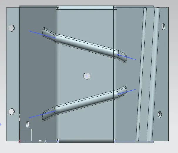
- Bead
- Unbend
- Rebend
- Hole
- flat pattern
- Drafting
Sketch
This command used for creating the sketch required for tabs, cut out, dimple, bead etc. 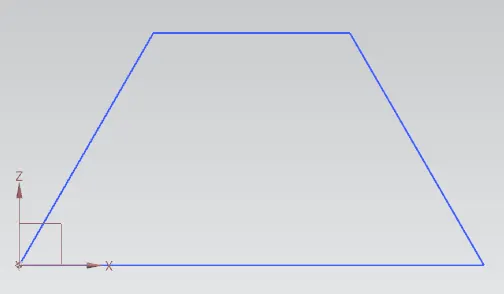
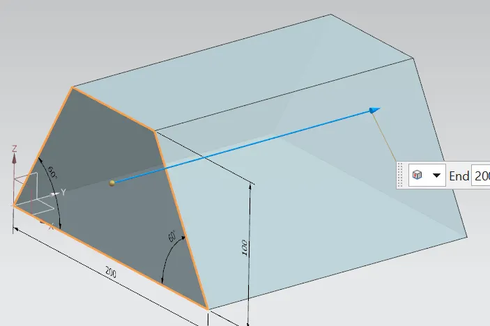
Extrude
To create a solid body other sheet metal we use extrude command and select the drawn closed 2D sketch and provide the length.
Sheet metal from solid
This command is used to convert a solid body surface into a sheet metal body of specified thickness. 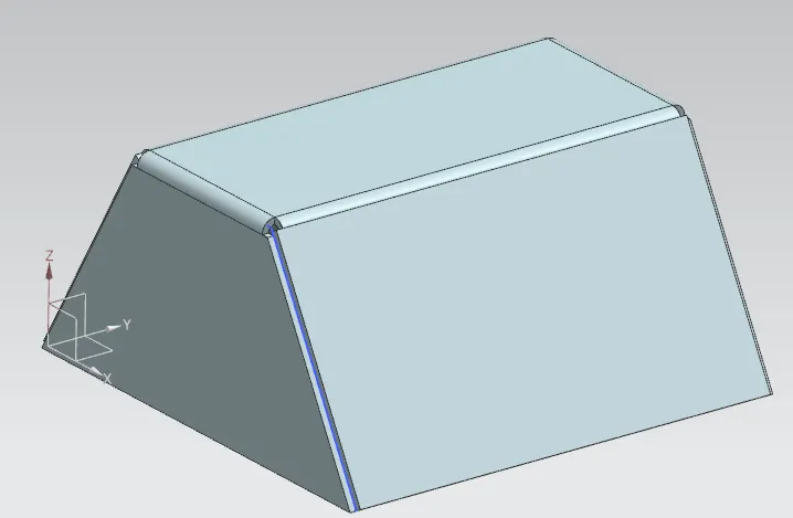
flange
This command is used for extruding a sketch along a specified vector to form a base feature. 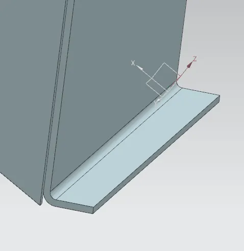
Bead
It is used for giving strength to the sheet metal. 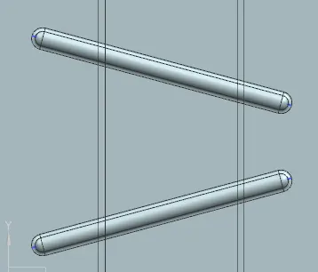
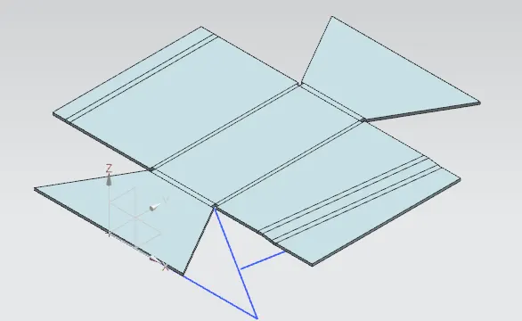
Unbend
This command is used to unbend the adjacent bends and flatten them back to tab.
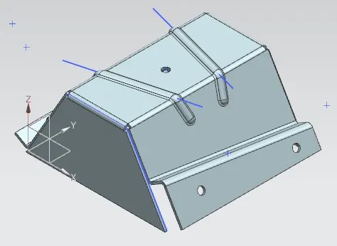
Rebend
This command is used for re bend the sheet metal.
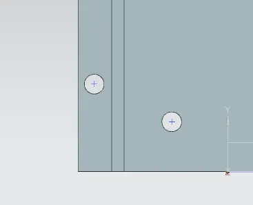
Hole
It adds holes on sheet metal parts according to the specified sketch points.
Flat pattern
After the object is completely finished and to produce the machining drawing we use flat pattern option to create the detailed flat sheet with all the features marked on it along with its description.
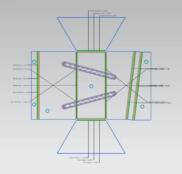
Drafting
We can convert the flat pattern of the model to a 2D draft on a drafting sheet. 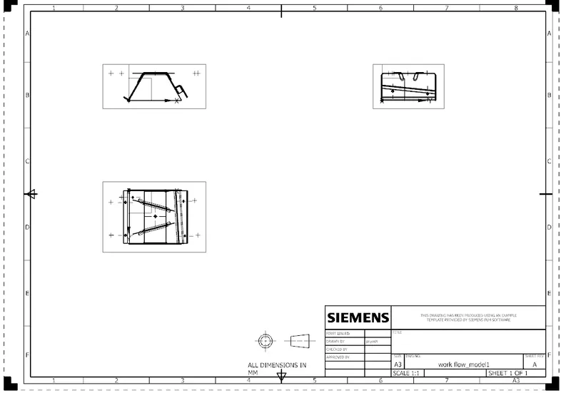
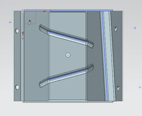
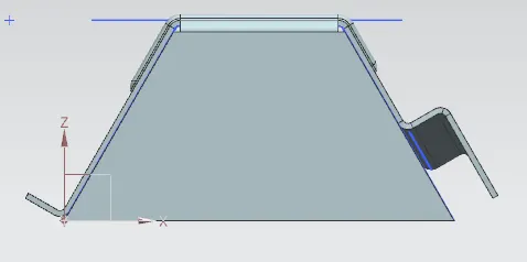
Conclusion
This project underlines the tools used for designing a odd shaped sheet metal box in NX cad software.