Advanced Sheet Metal Design Using NX Cad Challenge_5_Odd Shaped Enclosure
Modelling an Odd Shaped Enclosure in NX Sheet Metal
OBJECTIVE
The objective of the project is to design a sheet metal odd shaped enclosure using Sheet metal application in Siemens NX and a drawing sheet needs to be drafted for the designed model using drawing application in NX.
Introduction
Sheet metal is metal formed by an industrial process into thin, flat pieces. Sheet metal is one of the fundamental forms used in metalworking, and it can be cut and bent into a variety of shapes. Countless everyday objects are fabricated from sheet metal. Thicknesses can vary significantly; extremely thin sheets are considered foil or leaf, and pieces thicker than 6 mm (0.25 in) are considered plate steel or "structural steel".
Sheet metal is available in flat pieces or coiled strips. The coils are formed by running a continuous sheet of metal through a roll slitter.
Design Methodology
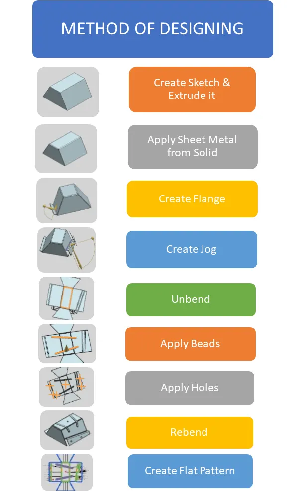
TOOLS AND FEATURES USED ON SHEETMETAL TO DESIGN ODD ENCLOSURE
- Sketch
- Extrude
- Flange
- Unbend
- Hole
- Bead
- Re bend
- Drafting
- Base view
TOOL AND FEATURE DESCRIPTION
- SKETCH
It is a 2d representation of a 3d part. It includes entities like line, rectangle, spline, circle, etc. It is a predetermined drawing with dimensions and relations.
- EXTRUDE
The sketch is extruded to some distance and results into a solid body.
- FLANGE
It is created with one or more edges at specified location. The minimum flange length must be at least four times the thickness of the sheet metal. Bend radius is equal to the
sheetmetal thickness.
- UNBEND
It makes the part unbend, that is all the features done are made flat. This is useful while sketching on the corners and bend areas.
5. Holes
Holes are added to provide alignment to enclosure. NX provides whole feature has options like general type, counterbore, countersink, etc.
Position, Diameter and depth are important inputs to apply hole to a body.
6.BEAD
It lifts material along the sketch. it strenghthen the product also increases the flex.
7.REBEND
This command puts back all the bends already created also along with new features included while in unbent state.
8.DRAFTING
This command is to have 2D drawing of the sheet metal part created.
9.BASE VIEW
It specifies the location, orientation, view and scale of the part for drafting.
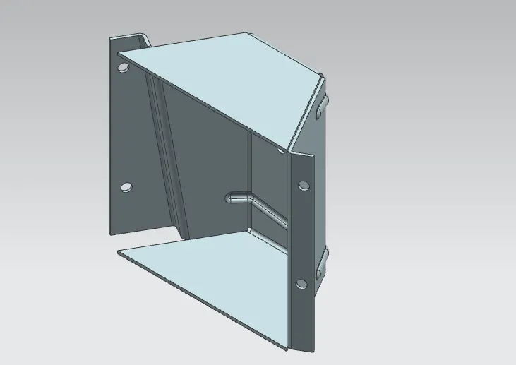
Odd Shaped Enclosure
(MODEL VIEWS)
Front View
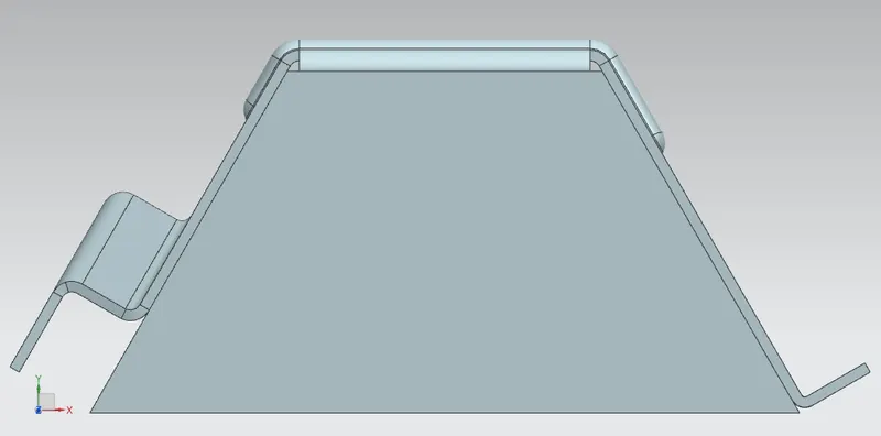
Side View
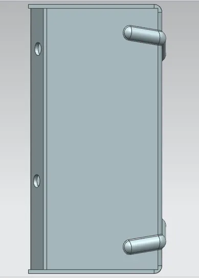
Top View
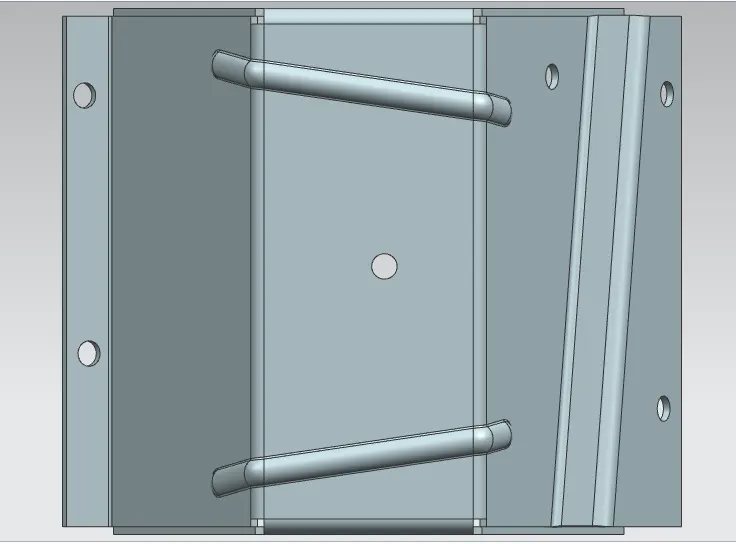
Isometric View
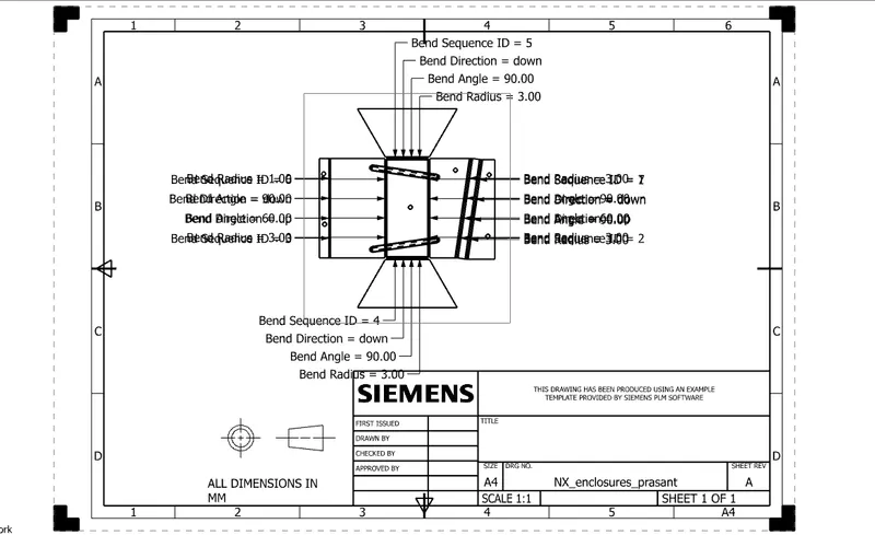
DRAFTING (Drawing Sheet)
It is refers to creating technical drawing that communicate about dimensions, view of component geometry and other features that performed over part in 2D or 3D. The draft of drawing is prepared which include annotation, dimension, relations, etc. which helps to a person from manufacturing or production department about component.
Conclusion
The sheet metal Recommended workflow to create enclosures with odd shapes or angles is successfully completed in NX_Cad.