Advanced Sheet Metal Design Using NX Cad (Box Assembly)
DESIGNING BOX ASSEMBLY WITH NX SHEET METAL
OBJECTIVE:
- Designing Box Assembly in NX Sheet Metal.
INTRODUCTION:
Sheet metals are flat metallic pieces having thickness of less than 6mm. Sheet metals have enormous Industrial as well Domestic use. We can see sheet metal products almost everywhere such as automobiles, aircrafts, containers, roofs, computer cabinets etc. It is very important for Design Engineers to be well worked with sheet metal design.
We are using NX (a mechanical design software) to design our Box Assembly.
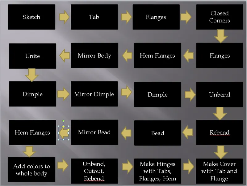
DESIGN METHODOLOGY:
DESCRIPTION:
Sketch - Creates a Sketch on the Plane Specified.
Tab - Adds material thickness to the sketch.
Closed Corner - Closes a corner where two adjacent flanges meet by extending bends and flanges.
Flange - Adds a flat flange at an angle to a planer face and adds a bend between the two.
Hem Flange - Folds edge on to itself.
Dimple - Lifts an area and operates like stamping tool.
Mirror Feature - Mirrors a feature across a plane.
Mirror Body - Mirrors a body across a plane.
Normal Cutout - Cuts material by projecting sketch onto it.
Unite - Combine two or more bodies into a single body.
Unbend - Flattens a bend and the material adjacent to the bend.
Bead - Lifts a material along the contour of a sketch that simulates a stamping tool.
Rebend - Restores an unbend feature to its previous bent state, along with any features added after the unbend feature.
IMAGES:
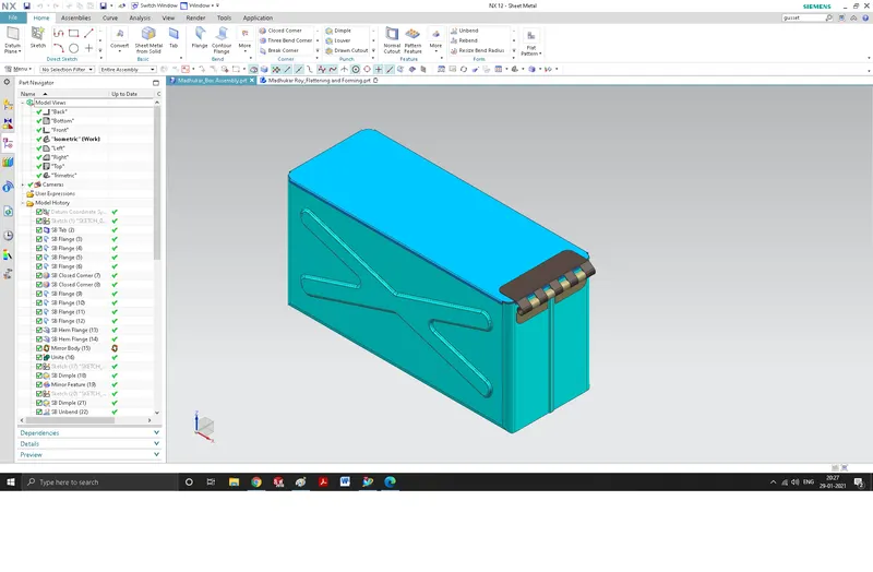
Isometric View:
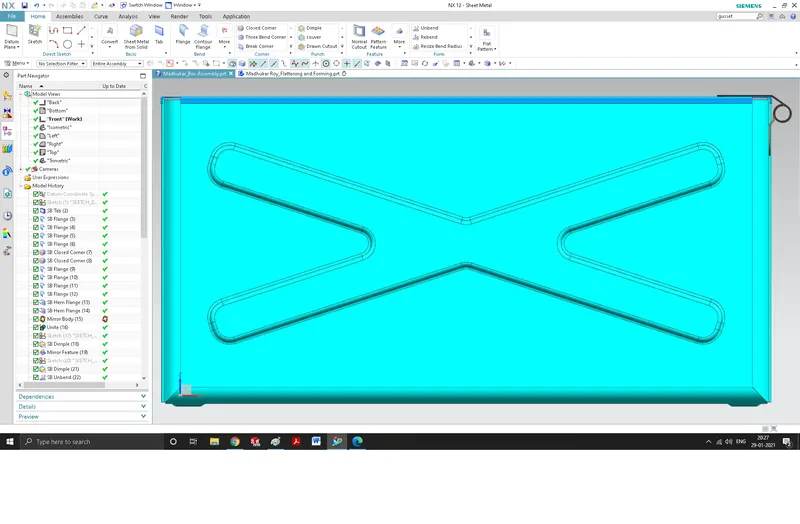
Front View:
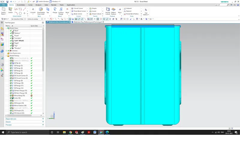
Left Side View:
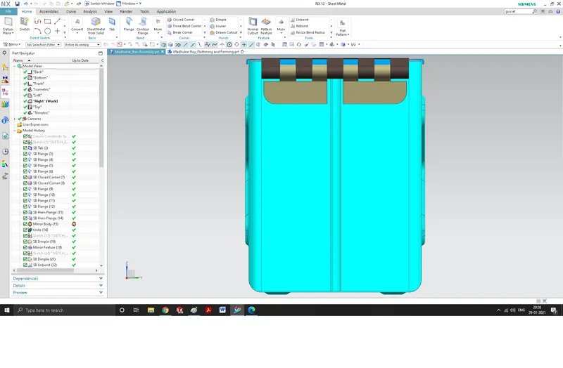
Right Side View:
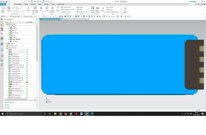
Top View:
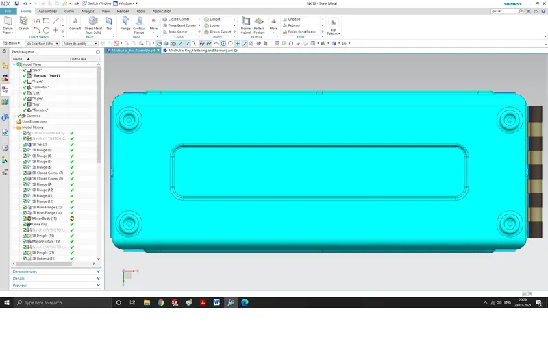
Bottom View:
CONCLUSION:
In this Project, we learned various sheet metal tools offered by NX such as Hem Flange, Bead, Normal Cutout etc. We obtained a sheet metal part named Box Assembly using these tools and got command over them.